Transformer rated isolation voltage when using multipliers

Thread Starter

SiCEngineer

Joined May 22, 2019
444
Hello everyone,

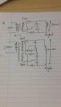
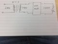
I have a small question regarding the voltage isolation rating of transformers if voltage multipliers are used on the secondary side.

I have attached an image to illustrate my text here.

Basically, would the transformer need to be rated above the secondary rated AC voltage (750V) or would it have to be rated to withstand the entire output voltage value (1500V?) in case of a fault, for example.

Thanks in advance
J
 

Attachments

dendad

Joined Feb 20, 2016
4,635
If one end of the secondary is at gnd potential, no. It will be ok. But if the multiplied voltage is at gnd, I'd think so.
 

SamR

Joined Mar 19, 2019
5,472
Short answer, NO. The transformer is only supplying 750V. The multiplication is typically a multistage diode/capacitor circuit and the transformer only "sees" 750V. Also, transformers are megged at much higher voltages than the rated output to test for insulation breakdown.
 

Thread Starter

SiCEngineer

Joined May 22, 2019
444
Sorry, realise my image could have been less abstract. I will attach another one, which shows two configurations.

In the first it is my assumption the transformer should be rated to withstand the 750V. In the second, it should be rated to withstand both windings combined (1500V). I'm just using arbitrary numbers here to try and illustrate it simply.

Thanks guys.
 

Attachments

dendad

Joined Feb 20, 2016
4,635
A 750V AC winding will give around 1KVDC out, so, in the top drawing, there is about +1KV on the winding.
The second drawing has around 1KV on the lower winding and 3KV on the second.
So, take into account, not only primary to secondary isolation voltage, but also secondary to secondary.
 

Thread Starter

SiCEngineer

Joined May 22, 2019
444
A 750V AC winding will give around 1KVDC out, so, in the top drawing, there is about +1KV on the winding.
The second drawing has around 1KV on the lower winding and 3KV on the second.
So, take into account, not only primary to secondary isolation voltage, but also secondary to secondary.
So although there is only 750VAC (1kVDC) on each of the windings, the second winding would have to be rated for a minimum of 3kVDC?
 

dendad

Joined Feb 20, 2016
4,635
I would think a transformer from a good manufacturer would withstand that, but you need to be well above the working voltage for safety.
Buy yourself a Megger Tester, but one with a few KV output will not be cheap I think.
Up to around 1KV, they are available for $50 or so. But you need higher than that. I'd say 5KV minimum.
 

ScottWang

Joined Aug 23, 2012
7,499
How much current do you need?
If the current does not that much, probably you can just use 250V:250V and voltages multiplier circuit.
 

Thread Starter

SiCEngineer

Joined May 22, 2019
444
How much current do you need?
If the current does not that much, probably you can just use 250V:250V and voltages multiplier circuit.
The current is pretty low, the main output is 250mA. I considered using a Cockroft walton (which I believe is the type of multiplier you mean?) however I believe that's for even lower currents.
 

SamR

Joined Mar 19, 2019
5,472
If you look at the PDF for your transformer you will find secondary RMS test voltage. Which is typically at least a 100x factor of the secondary rated voltage. Even on a 120/12/6 step-down transformer, it is 1500-2500V on its secondary windings.
 

Thread Starter

SiCEngineer

Joined May 22, 2019
444
If you look at the PDF for your transformer you will find secondary RMS test voltage. Which is typically at least a 10x factor of the secondary rated voltage. Even on a 120/12/6 step-down transformer, it is 1500-2500V on its secondary windings.
I haven't got a transformer PDF as of current. I am just curious as to how one could possibly mitigate some of the issues that exist with using transformer isolated step-up DC/DC converters, such as the parasitics, high voltage ratings of the transformer and the like. My vision is that by using voltage multipliers the transformer could be much easier to design and insulate than if it was to accomplish the entire step up itself.
 

Thread Starter

SiCEngineer

Joined May 22, 2019
444
At those volts, that is a pretty decent transformer!
250mA at 3 to 4KV will require a 1KVA or better transformer core.

How much voltage stability do you need?
What is your load?
Yep, the transformer is the key design element. The voltage needs to be very stable, which is another reason why I ruled out the Cockroft Walton series multiplier since the voltage regulation is quite poor. There is a parallel version which has much better regulation however (?).

It's for an aerospace application, which is another reason why I'm looking into this type of method. Ideally would run at high frequency to reduce the size of the converter but the parasitics of a high voltage transformer make that difficult.
 

dendad

Joined Feb 20, 2016
4,635
A high frequency switch mod supply may be the way to go, but as you discovered, the design at that power level is not trivial. My switch mode designs have been limited to 10s of watts only.
You may have to incorporate some sort of feedback and control for voltage regulation.
 

Thread Starter

SiCEngineer

Joined May 22, 2019
444
A high frequency switch mod supply may be the way to go, but as you discovered, the design at that power level is not trivial. My switch mode designs have been limited to 10s of watts only.
You may have to incorporate some sort of feedback and control for voltage regulation.
I have good experience in SMPS, and plan to use that technique. Can you not use voltage regulation/feedback on a cockroft walton type multiplier? And probably not best to drive a cockroft walton multiplier from a SMPS transformer?
 
Top