Facebook
 Google
 GitHub
 Linkedin
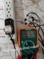
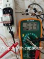
Ok, so, after doing some so called thinking, i multiplied the 36.7 rms unrectified voltage as shown in picture with original posted question by the square of 2 aka 1.41421356237 and got 51.901637738979. Even if the peak voltage gets through somehow uneffected by diode voltage drop, the cap shows 53.3. Sure this could be from tbe supply voltage ever so slightly increaseing and decreasing, but, i guess im wondering if its normal for peak voltage to be unaffected by diode voltage drop? Shouldn't peak voltage be reading at about 1.5 volts less on the output of a full wave rectifier? Also, considering the factors, why would a educated professional choose a cap to be installed in the mass production of a product that has a voltage essentially equal to and actually slightly less than the peak voltage of a tranformer?
Transformer output question
- Thread starter Energy forever
- Start date