Transformer output question

Thread Starter

Energy forever

Joined Sep 11, 2021
46
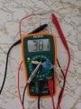
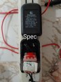
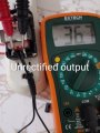
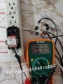
I have a power adapter that says it outputs 23 volts dc. I opened it up and measured 30 some volts right off the tranformer. With a 50 volt capacitor and full wave rectifier hooked up, the output reads 50 some volts. 1: Why is this happening? 2: How is the cap charging to a voltage higher than the supply? (Note; originally there was a small circuit installed to output of transformer, which had a full wave rectifier and a 50v 47uf cap, i removed it and hooked up my own components and both ways yielded the same output. Me not know why)
 

Attachments

MaxHeadRoom

Joined Jul 18, 2013
28,682
It is possible it is one of the early supplies that were not regulated, the voltage drops when the rated load is applied.
If so, it depends on the technology.
 

zophas

Joined Jul 16, 2021
165
The 50v marking on a capacitor is telling you what voltage the capacitor is rated at. Anything above this may destroy the capacitor and sometimes more. The voltage that a capacitor will charge to depends on the circuit it is attached to.
 

Thread Starter

Energy forever

Joined Sep 11, 2021
46
It is possible it is one of the early supplies that were not regulated, the voltage drops when the rated load is applied.
If so, it depends on the technology.
I was kinda thinking that too, but i still dont get how the cap charged 20 volts more than the output of the tranformer. I included pictures showing the cap is somehow charged to a voltage higher than the source. How is it possible for the cap to reach a higher voltage than it is supplied in this situation?
 

MrChips

Joined Oct 2, 2009
30,795
Your DC voltmeter is taking an average reading.
If there is no load on the capacitor then the capacitor will tend to capture the peak voltage including noise spikes.
 

Thread Starter

Energy forever

Joined Sep 11, 2021
46
Your DC voltmeter is taking an average reading.
If there is no load on the capacitor then the capacitor will tend to capture the peak voltage including noise spikes.
If the transformer was putting out 50 volts, why did the multimeter read 30 some? The only things hooked up are what is mentioned.
 

sagor

Joined Mar 10, 2019
909
The 24VDC rating at at a specific load. With little to no load, the voltage will be higher. The load for the 24VDC is specified as 60mA. Put a 60mA load on it first, then measure the voltages...
 

MrChips

Joined Oct 2, 2009
30,795
The transformer is not putting out 50V.

The transformer is spec'd as 60mA @ 23VAC. That is the spec when loaded.
So with no load you measured 30VAC. It is normal for a transformer to output a much higher voltage when there is no load. For a 60mA transformer, the manufacturer can get away with very thin wires in the windings. This adds internal resistance in the transformer.
30VAC is 42V peak. Any noise on top of that will be captured by the capacitor. There is no discharge path to bring the voltage down in between peaks. A diode feeding a capacitor with no load is a peak detect circuit.

1633307951320.png
 

Thread Starter

Energy forever

Joined Sep 11, 2021
46
Ok, so, i twisted together 26 10k resistors and hooked it up and sure enough, output was right around what the label said. Guess im just used to modern day precision. I woulda put a higher voltage cap in that circuit tho, if i designed it to have one.
 

Attachments

MrChips

Joined Oct 2, 2009
30,795
This is not about modern day precision. This is about knowing that power sources have internal resistance that must be taken into account.
 

Thread Starter

Energy forever

Joined Sep 11, 2021
46
This is not about modern day precision. This is about knowing that power sources have internal resistance that must be taken into account.
Seems you misunderstood me, modern day supplies have an output usually precisely as labeled. Ever measure a 5 volt supply for a modern day cell phone telephone? That's the modern day precision im used to. Unlike this old power supply output that is far from what is labeled and hence less precise. So, precisely what resistance would i need to account for when it comes to modern day power supplies such as those for modern cell phone telephones?
 

MrChips

Joined Oct 2, 2009
30,795
You misunderstand power supplies.
What you have is an unregulated power supply.

Smart phones plug into a USB charging port.
USB ports have more stringent specifications, 5VDC ± 5% under load which translates to 4.75V to 5.25V. This requires a regulated output.

Let us do some simple application of Ohm's Law.

1) If a power supply output voltage falls from 50V to 25V while delivering 50mA, then the internal resistance is 25V/0.05A = 500Ω.

2) If a power supply output voltage falls from 5V to 4.75V while delivering 500mA, then the internal resistance is 0.25V/0.5A = 0.5Ω

Notice the difference?

An ideal voltage source has 0Ω internal resistance, i.e. the voltage remains constant independent of the load current.
Again, this is not about modern day precision. This is about knowing how circuits behave. And that is what AAC is all about. We're here to assist you.
 

MaxHeadRoom

Joined Jul 18, 2013
28,682
Seems you misunderstood me, modern day supplies have an output usually precisely as labeled.
Modern WALL-Wart PS are regulated to the greater extent, what you show is a simple transformer, not the SMPS type that the modern ones usually are.
Older style were of the simple type that you show. that relies on the load to bring the voltage down.
 

Thread Starter

Energy forever

Joined Sep 11, 2021
46
You misunderstand power supplies.
What you have is an unregulated power supply.

Smart phones plug into a USB charging port.
USB ports have more stringent specifications, 5VDC ± 5% under load which translates to 4.75V to 5.25V. This requires a regulated output.

Let us do some simple application of Ohm's Law.

1) If a power supply output voltage falls from 50V to 25V while delivering 50mA, then the internal resistance is 25V/0.05A = 500Ω.

2) If a power supply output voltage falls from 5V to 4.75V while delivering 500mA, then the internal resistance is 0.25V/0.5A = 0.5Ω

Notice the difference?

An ideal voltage source has 0Ω internal resistance, i.e. the voltage remains constant independent of the load current.
Again, this is not about modern day precision. This is about knowing how circuits behave. And that is what AAC is all about. We're here to assist you.
You are referring to a load as internal resistance. If you wanna help me you can do so either by staying off my threads or learning how to speak to me properly.
 

Thread Starter

Energy forever

Joined Sep 11, 2021
46
Modern WALL-Wart PS are regulated to the greater extent, what you show is a simple transformer, not the SMPS type that the modern ones usually are.
Older style were of the simple type that you show. that relies on the load to bring the voltage down.
What was the point of saying that?
 

Tonyr1084

Joined Sep 24, 2015
7,899
30VAC is 42V peak.
This is the only reference to "Peak" voltage. How do we arrive at this number? 30VAC is the RMS value, or practical useful voltage. When you rectify it and filter it with a capacitor you no longer get the RMS value you get the "Peak" DC voltage. This is calculated using the square root of 2 (a.k.a 1.414). So 30V times 1.414 comes to 42.42 volts DC. There are other concerns as well. The rectifier will drop some voltage, depending on the type of rectification used. A single diode will drop approximately 0.6 volts whereas a full wave bridge will drop twice that, or 1.2V.

I mention this because, aside from Mr Chips' comment is the only closest thing to explaining why you see a higher voltage when rectified and filtered. Since the potential output of the transformer when rectified is 42V, a capacitor rated for 42 volts or higher is in order. And you're not going to find caps rated in that specific voltage, hence, the 50V cap. Also worth noting is that caps have a percentage rating as well. Off hand I don't know what typical tolerances are for caps but I would imagine that a 50 volt cap with a ±10% means it can be relied upon to 10% below its rated voltage, or in the case of a 50V cap, 45V would be a safe assumption.

When engineering a circuit tolerances need to be considered as well. I wouldn't use a 50V cap on a 50VDC system; there's a chance of failure. 133 to 150% over rating is common in engineering circles. Hobbiests like double values as opposed to the 1 1/2 times thing. But in the commercial world, 133% is common whereas in life/mission critical circuits 150% to 200% is normal.
 

Tonyr1084

Joined Sep 24, 2015
7,899
What was the point of saying that?
Switch Mode Power Supplies (SMPS) use high frequency PWM (Pulse Width Modulation) to achieve a specific DC voltage whereas a simple transformer simply transforms one voltage (AC) into another VAC. On a 10:1 transformer it will change 120VAC into 12VAC. IF the voltage on the line changes to - say - 117VAC then the transformer is going to convert that to 11.7V. Hence transformers are dumb devices whereas SMPS uses feedback to regulate the output voltage and maintain the 5V mentioned within a tolerance regardless of how the main voltage may change. The 5V output current rating depends on the circuitry and its capability. Weaker 5V supplies may deliver 700mA of current whereas stronger 5V supplies can deliver 1200mA (or 1.2A) of current.
 

Thread Starter

Energy forever

Joined Sep 11, 2021
46
The 50v marking on a capacitor is telling you what voltage the capacitor is rated at. Anything above this may destroy the capacitor and sometimes more. The voltage that a capacitor will charge to depends on the circuit it is attached to.
Is that why the capacitor charged to a voltage higher than the source?
 

Thread Starter

Energy forever

Joined Sep 11, 2021
46
This is the only reference to "Peak" voltage. How do we arrive at this number? 30VAC is the RMS value, or practical useful voltage. When you rectify it and filter it with a capacitor you no longer get the RMS value you get the "Peak" DC voltage. This is calculated using the square root of 2 (a.k.a 1.414). So 30V times 1.414 comes to 42.42 volts DC. There are other concerns as well. The rectifier will drop some voltage, depending on the type of rectification used. A single diode will drop approximately 0.6 volts whereas a full wave bridge will drop twice that, or 1.2V.

I mention this because, aside from Mr Chips' comment is the only closest thing to explaining why you see a higher voltage when rectified and filtered. Since the potential output of the transformer when rectified is 42V, a capacitor rated for 42 volts or higher is in order. And you're not going to find caps rated in that specific voltage, hence, the 50V cap. Also worth noting is that caps have a percentage rating as well. Off hand I don't know what typical tolerances are for caps but I would imagine that a 50 volt cap with a ±10% means it can be relied upon to 10% below its rated voltage, or in the case of a 50V cap, 45V would be a safe assumption.

When engineering a circuit tolerances need to be considered as well. I wouldn't use a 50V cap on a 50VDC system; there's a chance of failure. 133 to 150% over rating is common in engineering circles. Hobbiests like double values as opposed to the 1 1/2 times thing. But in the commercial world, 133% is common whereas in life/mission critical circuits 150% to 200% is normal.
After taking the time to write that, you still didn't explain how the capacitor reached a voltage higher than the source. Even in the scenario 42 volts was peak, that still aint the 50 some volts i shown in picture with cap. Furthermore, taking into account diode drop the voltage at cap should be lower not higher than input, not to mention the small but still present filtering effects diodes have to weed out so called noise spikes. So, how is the cap charging higher than source?
 
Top