 Facebook
 Google
 GitHub
 Linkedin
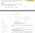
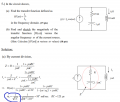
May someone explain the reason of the substitution of W0 that is circled in each picture. I understand how to find the transfer function but not the W0 substitution. Why do we substitute different variables for W0 in each of the question?
Attachments
-
 184.2 KB Views: 20
 -
 94 KB Views: 22
 -
 130.7 KB Views: 24


