Total novice needs advice on zener diode

Thread Starter

emmajackt

Joined Dec 2, 2018
11
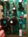
Hi, I am a total novice when it comes to circuit boards and was wondering if someone could help me. I have a Horizon Omega CS treadmill and there was a loud bang when I plugged it in last week and the circuit board had blown a couple of transistors and a couple of zener diodes. As the diodes have blown, I am unable to test what voltage ones I would need to replace them. I am attaching a picture and would be really grateful if someone could help me. I have looked online for a diagram of the circuit board with no luck

Thank you, Kev.
 

Attachments

spinnaker

Joined Oct 29, 2009
7,830
I think you are going to need a schematic. Try searching on line.

.But you are also going to need to figure out what could have caused the bang. A schematic can help with that too,
 

MisterBill2

Joined Jan 23, 2018
18,173
The picture provides very little information about the diodes, other than a cluie as to their physical size. That reduces the options to about 2000 parts. We see them designated as ZD1 and ZD2, which relate them to some drawing and some parts list, neither of which we can see.

Then there is another concern, which is that the parts did not fail just because of no reason. Something caused that failure and without fix in the problem a second set of parts will also fail.So first you need to know what caused the destruction, and repair that problem first. OR, was it a bolt of lightning struck at just the instant that you plugged the thing in?
 

Thread Starter

emmajackt

Joined Dec 2, 2018
11
The picture provides very little information about the diodes, other than a cluie as to their physical size. That reduces the options to about 2000 parts. We see them designated as ZD1 and ZD2, which relate them to some drawing and some parts list, neither of which we can see.

Then there is another concern, which is that the parts did not fail just because of no reason. Something caused that failure and without fix in the problem a second set of parts will also fail.So first you need to know what caused the destruction, and repair that problem first. OR, was it a bolt of lightning struck at just the instant that you plugged the thing in?
Hi,Thanks for your quick reply. The diodes that I need are the same as the one in the picture and i didn't know if the voltage could be ascertained from the stripes on it. As I have said, I know nothing about electronics and was just going to have a go and see if I could fix it myself. Nothing else on the board looks as though its blown apart from the two diodes, two transistors and a 68k ohm 1w metal oxide resistor.Is there something that I should be looking for, that usually causes these to blow? Thanks for your help, I really appreciate it.
Regards, Kev.
 

dl324

Joined Mar 30, 2015
16,845
I know nothing about electronics and was just going to have a go and see if I could fix it myself.
That's a pretty tall order. Simply replacing failed components might fix the problem, but, more likely, it won't. Something caused the components to burn up and not addressing that cause would likely result in more burned components.

Without a schematic, we won't be able to help you. If you can't trace the components to create one, at least for the circuitry involved, there's not much anyone can do to help you.

Post well focused, close ups of the failed components. Diodes and transistors are large enough to have part numbers marked on them.
 

Ylli

Joined Nov 13, 2015
1,086
The picture shows one zener diode designator (ZD1) and one signal diode designator (D12?). The other diode in the picture is a signal diode and *may* be the same as the missing one. Probably could use 1N4148's. As for the voltage of the zener, more information is required.
 

spinnaker

Joined Oct 29, 2009
7,830
Hi,Thanks for your quick reply. The diodes that I need are the same as the one in the picture and i didn't know if the voltage could be ascertained from the stripes on it. As I have said, I know nothing about electronics and was just going to have a go and see if I could fix it myself. Nothing else on the board looks as though its blown apart from the two diodes, two transistors and a 68k ohm 1w metal oxide resistor.Is there something that I should be looking for, that usually causes these to blow? Thanks for your help, I really appreciate it.
Regards, Kev.

I see a silk screen of the diodes. Not the diodes themselves. Doubt they are what caused the "loud bang" anyway. You might also have something else blown that does not look like it is blown.

You might be better just to order a whole new board.
 

MisterBill2

Joined Jan 23, 2018
18,173
The picture shows one zener diode designator (ZD1) and one signal diode designator (D12?). The other diode in the picture is a signal diode and *may* be the same as the missing one. Probably could use 1N4148's. As for the voltage of the zener, more information is required.
Probably the other diode was NOT a signal diode but a power diode of some kind. So just putting ia diode without understanding what kind is a poor choice. And still there is the question as to why all of those parts just fried. That does not happen "for no reason", but rather because something else is wrong someplace. So an investigation into the rest of the treadmill is in order to see what else may be damaged. It could be that the insulation wore through on a wire some place and that the resulting short circuit lead to the problem. AND, if you can change the title of this post to "Horizon Omega CS treadmill DISASTER", somebody with a circuit diagram may suddenly appear. There is a whole lot of knowledge available in there forums, but mostly to find it you must pose the right questions, since very few mind-readers are among the group. And I see that it looks like two transistor devices were destroyed. Determining what those devices were will also be a interesting challenge. So it will be very useful to include a photo of the whole circuit board.

And, you definitely need to check out the whole treadmill and all of the wiring before replacing the whole circuit board, so as to avoid doing the same damage to a new and expensive board as well. I am certain that there is an additional problem someplace else.
 
Last edited:

Thread Starter

emmajackt

Joined Dec 2, 2018
11
Huh??????
Thank you for all your answers. I didn't realise it would be so difficult, as I thought if I could find the voltage of the diodes, I could replace them along with the blown transistors and see if it worked. The treadmill is old and not worth much at all and a new board would be far too expensive, so that is not an option. Now I know that the diodes may be different types, I don't think I'll bother repairing it. I have attached more photos of the complete board, just in case someone can see something that I have missed, but if not, thanks again for all your replies, I really appreciate it.

Regards, Kev.
 

Attachments

dl324

Joined Mar 30, 2015
16,845
C13 looks like it leaked. Can you post pictures with better focus?

Replacing components without trying to understand what caused them to fail is usually a waste of time and money.
 

spinnaker

Joined Oct 29, 2009
7,830
Thank you for all your answers. I didn't realise it would be so difficult, as I thought if I could find the voltage of the diodes, I could replace them along with the blown transistors and see if it worked. The treadmill is old and not worth much at all and a new board would be far too expensive, so that is not an option. Now I know that the diodes may be different types, I don't think I'll bother repairing it. I have attached more photos of the complete board, just in case someone can see something that I have missed, but if not, thanks again for all your replies, I really appreciate it.

Regards, Kev.

Have you tried searching for a schematic?
 

Thread Starter

emmajackt

Joined Dec 2, 2018
11
Have you tried searching for a schematic?
I have tried searching for a schematics, but cannot find one. It is an old treadmill and not worth spending £££s on. I just thought if I could find what type of diodes they were, I would replace them along with the two blown transistors, and blown resistor and hope for the best.

Regards, kev.
 

Ylli

Joined Nov 13, 2015
1,086
Is there anything more (or different) that you can add about the treadmill manufacturer of model number? The only thing I can find online on the "Horizon Omega CS" is a replacement belt.
 

MisterBill2

Joined Jan 23, 2018
18,173
If there are stripes remaining on the diodes then we can get a number and possibly know what they were. How bad off are the transistors?
AND, None of the photos show the area that the parts were removed from so they are not pictures of the whole board. Also, I was only able to expand the image of the first one, I am not sure why that is. In addition, 21k is not a very high resolution picture at all.
When I asked for a photo of the whole board I really didmean the entire board in one picture, which is not what we got.
 

Thread Starter

emmajackt

Joined Dec 2, 2018
11
If there are stripes remaining on the diodes then we can get a number and possibly know what they were. How bad off are the transistors?
AND, None of the photos show the area that the parts were removed from so they are not pictures of the whole board. Also, I was only able to expand the image of the first one, I am not sure why that is. In addition, 21k is not a very high resolution picture at all.
When I asked for a photo of the whole board I really didmean the entire board in one picture, which is not what we got.
Hi, I have attached a picture of a board that I found online. It is the same as mine. The two diodes ZD1 and D20 are the blown ones, along with the transistors behind them. Hope this helps.
Regards, Kev
 

Attachments

MaxHeadRoom

Joined Jul 18, 2013
28,617
By the look of it it is a PWM controller, most older ones were SCR bridge type, if PWM it most likely has a at least one power Mosfet thet may have blown, one source for boards is ebay.
Max.
 

MisterBill2

Joined Jan 23, 2018
18,173
I went through the service manual cover to cover and while it shows a picture of the board it is not useful. BUT the board has all kinds of surface mount parts on the underside, so it is actually quite complex. The one puzzle was the statement about if the line voltage was too low there could be damage. That one statement tells me that there were shortcuts taken in the design, leaving it open to damage from under-voltage.

So now comes a question about how much effort and expense you are willing to take to make it like it was. Making a treadmill run at an adjustable speed using a simple speed controller is not hard, but having all of those nice functions that it originally had is a different story altogether. Running the slope adjustment motor from a power supply is not complex, but doing it from the control console certainly could be. There is also the question as to what speed you want it to run at, and do you want the speed continuously variable or not. Speed controls for brush type motors can be quite simple and fairly cheap, but they are less efficient than the very best control system. So it all gets down to a question of what it is that you would be happy with.
 
Top