Toroidal Transformer Design

Thread Starter

rennie1080

Joined Apr 10, 2017
52
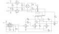
There is a design. In the design 6V AC signal is transformed to +-12V DC signal by using transformer. I try to understand the design. Transformers are toroidal type. I dont know number of turns. ( How can I determine that ? ) Could you help me how the circuit works ? I add the design.


Attachments

Dodgydave

Joined Jun 22, 2012
11,307
Don't understand why you have two transformers,?? just use one transformer and use a ratio of 2:1 or 3:1, this will give you 12V ac out or 18V ac, depending on losses, then feed that into your bridge rectifier. ..

The number of turns depends on the size of torroid, wire thickness, turns ratio.
 

Thread Starter

rennie1080

Joined Apr 10, 2017
52
Actually I dont know why they use 2 transformer. I try to understand that transformer system. I add the photo of the part.
 

Janis59

Joined Aug 21, 2017
1,849
The thumb rule of trafo calc:
Measure the cross section of core, cm2. In the toro case it is width of steel to height of stack.
Apply the formula turn number to each Volt = 50/Section area.
Correct this formula: as much more You have the frequency comparing to 50 Hz, as less You wind. Example: 50 kHz means 1000-fold less turns. Next correction, this formula is decided for 1 Tesla, but ferrites mostly uses 0,25 T, thus You must wind 4 times more turn count. Last correction - this formula is for sinusoidal, but You probably have a meandric form of signal. Then wind 1,11-fold more. Example, Your ferrite toro is 2,5cmx2cm at 50 kHz. Then apply the t/V=50/2,5/2/1000*4*1,11=0,044 turns per each Volt. Thus the typical 220 V network having 310 V DC after full-wave rectifier demands at least 3,1*4,4=15 turns.
Next problem is wire diameter: apply the J=3,5 A/mm2. Then for wire cross section pi()/4*D^2 You get J=i/section or i/J=section. Therefore pi()/4*D^2=i/J or D=sqrt(i/J/pi()*4).
Last problem is max power (gabarite power). Calculate the cross section of window (the circle inside the donough). Calculate the mm2. Immagine that half is primary winding and other half is secondary. Immagine that secondary consists of one alone turn producing the voltage 1/(turns to Volt). Just use the figure You have, just make it reciproke. The such wire current will be evaluated as i=J*section of this halve. And i*U=power, voila. No, actually You need to get some 20% of this area to insulation, some 22% to wire roundness caused air gaps, some 10% to wire insulation thickness, some 20% to inexact winding overlapping angles etc etc, thus the real factor (labeled as filling factor with the copper) is about 0,2 for tiny wire (d=0,06-0,2 mm) or 0,3 (d=0,2-0,8 mm) or 0,4 (d>1mm).
This methodology is probably not ideal very much scientifically, but it works damn good.
 

Janis59

Joined Aug 21, 2017
1,849
RE:""I dont know number of turns. ( How can I determine that ? )""
The best way is to COUNT it!!! In the picture I see the 4 turns! Do You see another count??
 

ebp

Joined Feb 8, 2018
2,332
The circuit seems very strange. What is it used for (i.e. what type of equipment)?

My first suspicion is that they wanted to minimize the capacitive coupling between the input and output sides.
There can be a lot of capacitance between the windings on a toroid. By using two transformers with just a few turns on the coupling "link" between the two of them, the capacitance can be minimized. A similar technique can be used for extremely high isolation voltage - which is sort of suggested by the insulation on the "input" transformer secondary - but then there is that 3.3 pF capacitor and trim pot.

Another possibility is that that there simply isn't enough window area in the toroids to get the winding shuttle through to put both primary and secondary on the same core. Of course a larger core would have solved that problem.

The cores are almost certainly ferrite. It is extremely unlikely they are iron. My guess is that the overall turns ratio is about 1:3

The bridge rectifier is an ordinary low-frequency type. Normally one would use fast recovery diodes, however the switching frequency must be rather low so the losses in the slow diodes are probably OK.

The 555 is configured to produce a reasonably good approximation of a square wave and the output and discharge pins are used as complementary outputs. This configuration is only successful with CMOS versions of the 555 because of the rail-to-rail swing of the output pin.
 

Thread Starter

rennie1080

Joined Apr 10, 2017
52
Thank you for your answers. I've found something about the circuit. 112:4 step down transformer and 4:380 step up transformer are used in the circuit. But I dont know so much about toroidal transformers. Does 112:4 mean that 112 is number of turn of thin wire and 4 is thick wire on the transformer? Am I right ?
 

ebp

Joined Feb 8, 2018
2,332
1:3 wasn't a bad guess! 112:380 = 1:3.4

Yes, the fine wire is the large number of turns and the heavy wire is the 4 turns. With toroidal transformers, it is really only what passes through the "hole" that counts as a turn. A single straight wire that is several centimetres long (or metres long) that just goes through the hole is counted as a "turn". The fact they used 4 turns on the coupling windings was probably largely a matter of convenience. As long as the total ratio of 112:380 was maintained they could have used other variations of turns counts.

Toroids tend to "contain" the magnetic flux in a way that reduces coupling to or from the winding except to/from other windings that pass through the hole. They are regarded as "self-shielding". Coupling is not perfect, so spreading out the 4 turn windings over the full diameter of the core improves coupling between the secondary and the primary.
 
Top