Facebook
 Google
 GitHub
 Linkedin
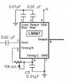
I bought an IC named LM567 from the market and wanted to use this an a bandpass filter which would give a low output when the input signal to it was 40kHz. In all other conditions and no input signal condition, as per the datasheet states, the output at pin 8 should be a high.
But while connecting the circuit as per the datasheet, the output pin 8 does not give a logic high while there is no input to it. Should not it give a high output as soon as the IC gets the supply Vcc and there is no input to it?
And one more question is that how much input voltage can I give to this IC ? In one equation in the datasheet, I read that the input should not exceed 200mV RMS. However, in maximum input column there was Vcc+0.5 volts. So does this mean that the input can be a 200mV signal riding on Vcc ? Or can I feed pure AC signal with RMS value nearly equal to Vcc ?
Waiting for replies. Thanks in advance.