Facebook
 Google
 GitHub
 Linkedin
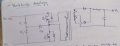
Hello, I'm building an Smps using tl494 chip for a stepper motor and I got 36 or 37 volts dc from the secondary filter capacitor. I want to regulate it at 36.00v. I've followed the diagram shown below from the datasheet. I've changed the resistor values from what's available to me. I've used 4.7k ohm for R3, 10k pot for R4, 67k resistor for R8, 5k for R8, 470 ohm for R5, 47k for RF.
The voltage regulation is not happening. I'm also confused about the ground pin which is connected to R9, is it the same ground pin connected to pin 7 of the tl494? If not what is the relationship between the two grounds? How can I successfully regulate the voltage if Vo is referenced from the secondary ground?
I'm using half bridge topology with center tapped secondary. I've tried the output dc with a stepper motor and it perfectly drives the stepper without an issue. I just wanted to get a stable voltage.