TL494 charger output voltage adjustment

Thread Starter

Mori_1234

Joined Apr 8, 2023
16
Hello Everyone,
Happy New Year!

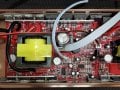
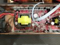
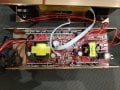
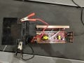
I have an issue with a TL494-based charger as part of a 12VDC to 220VAC inverter-charger system which I have recently purchased.

The output voltage of the charger is set to 14.3 volts which is too high based on the battery's specification for float/standbye applications; it should be max 13.8V. This causes the (SLA) battery to become too warm which will probably reduce its life cycle.

As the design lacks potentiometer, I was wondering how to reduce the output voltage from 14.3 to 13.8 volts?

I've attached some photos of the board and an extracted schematics as far as accessible without dismantling the assembly.

Any inputs are aporeciated. IMG_20250108_234754817.jpgIMG_20250108_235829069.jpgIMG_20250108_235818583.jpg
 

Attachments

Thread Starter

Mori_1234

Joined Apr 8, 2023
16
Hi guys,
I'm sorry, I think I got the wrong portion of the circuit as the charger. The inverter circuit uses two TL494 IC's; I wrongly thought one is related to the charging circuit. So, I need to study the circuit more carefully ; I'm still unable to identify the charging circuit.

Still, any hint on how the charging voltage is managed in a inverter+charger system is highly appreciated.

My appologies for my misleading original post.
 

PhilTilson

Joined Nov 29, 2009
152
I may be missing something, but another concern could be that the charger as specified looks as though it is designed for lead-acid batteries which float at around 14.3V. The new configuration looks as though it is intended for Li-Ion batteries (13.8V) so you need to look at charging protection as well as charger output voltage.
 

Thread Starter

Mori_1234

Joined Apr 8, 2023
16
I may be missing something, but another concern could be that the charger as specified looks as though it is designed for lead-acid batteries which float at around 14.3V. The new configuration looks as though it is intended for Li-Ion batteries (13.8V) so you need to look at charging protection as well as charger output voltage.
Hi Phil, thanks for your input.

It's basically a UPS-like modified sine-wave inverter+charger combo device which passes through the mains electricity to the load when the mains electricity is present, or inverts the battery to 220AC with very small delay when there's outage.

The sealed acid battery spec mentions float/standbye voltage within 13.38-13.68 V.

Any idea, based on your experience, how the charging voltage is managed in such inverter +charger combo device?

I'm including some photos of device, circuit board and the battery's name plate to clarify.

1000042274.jpg

1000042273.jpg

1000042161.jpg
 

crutschow

Joined Mar 14, 2008
38,322
Yes, exactly!
Always stuck on 14.3V
So that would involve whatever circuitry changes the output from Equalizing to the Charging voltage.
Hard to fix that without a schematic of the device. :(

It might be possible, of course, to add an external circuit to do lower the charging voltage, if that is something you would consider.
 

Thread Starter

Mori_1234

Joined Apr 8, 2023
16
So that would involve whatever circuitry changes the output from Equalizing to the Charging voltage.
Hard to fix that without a schematic of the device. :(

It might be possible, of course, to add an external circuit to do lower the charging voltage, if that is something you would consider.
Hi crutschouw,
Thanks for the input. As the last resort, why not. I find it a pity to throw out the thing. You can kindly give me your idea, I will try to work it out myself. Thanks
 

crutschow

Joined Mar 14, 2008
38,322
give me your idea, I will try to work it out myself
One tricky part is to separate the charging from the discharging of the battery.
Could an AC relay be used to detect the incoming mains voltage and assume that the battery is only discharging when the AC is not detected?
 

Thread Starter

Mori_1234

Joined Apr 8, 2023
16
One tricky part is to separate the charging from the discharging of the battery.
Could an AC relay be used to detect the incoming mains voltage and assume that the battery is only discharging when the AC is not detected?
Hi. There's already a relay inplemented for the purpose you mentioned. Let me work on this. Thanks
 

Thread Starter

Mori_1234

Joined Apr 8, 2023
16
Hi Mori_1234,
You could add a diode right into de charging line. Just cut it up and solder the diode. it could lower it to 13.7 VDC.
Thanks
Hi Jorge. Thanks for the input. The current flowing to the battery could rise to 10 A or more (I have to check the current when the battery is depleted) I guess a diode with proper rating could do the trick. The advantage is simplicity. Thanks.
 

crutschow

Joined Mar 14, 2008
38,322
The current flowing to the battery could rise to 10 A or more
You would also need an inverse parallel diode for the current flowing out of the battery during AC power loss.
Or is there a separate wire from the board for battery charging and discharging?

Also reducing the charge voltage may not allow the battery to fully charge, leading to battery sulfation.
 
Hi Jorge. Thanks for the input. The current flowing to the battery could rise to 10 A or more (I have to check the current when the battery is depleted) I guess a diode with proper rating could do the trick. The advantage is simplicity. Thanks.
Hi Mori_1234, thanks for appreciate it. Just a thing, 10 A maybe brake the battery. Normally, in charging, is ten per cent (10%) the batteries reference in order to get a durable life cicle.
Thanks a lot
Jorge
 

Thread Starter

Mori_1234

Joined Apr 8, 2023
16
Hi Mori_1234, thanks for appreciate it. Just a thing, 10 A maybe brake the battery. Normally, in charging, is ten per cent (10%) the batteries reference in order to get a durable life cicle.
Thanks a lot
Jorge
Hi Jorge, thanks for the warning. It seems there are too many issues with this device: charging voltage constantly on 14.3, charging current too high...
I will take a second look at the circuit (I need to disassemble all power diodes and transistors fixed on the housing) to see if I can understand its working and whether I can improve it, otherwise, I will put the whole thing aside.
 

Thread Starter

Mori_1234

Joined Apr 8, 2023
16
You would also need an inverse parallel diode for the current flowing out of the battery during AC power loss.
Or is there a separate wire from the board for battery charging and discharging?

Also reducing the charge voltage may not allow the battery to fully charge, leading to battery sulfation.
Hi crutschow, thank you so much for your valuable inputs.

I will take a second look at the circuit (I need to disassemble a full array of power diodes and transistors fixed on the housing) to see if I can understand its working and whether I can improve it. Otherwise, I will put the whole thing aside.
 

Thread Starter

Mori_1234

Joined Apr 8, 2023
16
Hello guys,

I teared down the inverter-charger, but, to tell you the truth it was too difficult for me to grasp and try to mod. So, finally, I settled for the diode solution thanks to Jorge. I had to use two diodes in parallel reverse to enable sink and source the current needed during charging and inverting. Now everything works much better ; the charging voltage floats at 13.6 volts and my battery no longer gets too warm. Thank you everyone especially Jorge and Crutschow. Cheers.
 
Top