 Facebook
 Google
 GitHub
 Linkedin
Hello everyone,
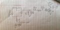
I was studying a tl494 based half bridge smps
I came across the current sense section opamp pin 15 & pin16
Now pin16 is connected directly to the ground
But there is some arrangment made to pin 15
I have drawn a part of it
Please can anyone help me what is a purpose of “103 trimpot” and why does the transistor “ 2n2222a” is also used which Is connected to microcontroller pic18f452
Attachments
-
 1.2 MB Views: 42


