Tl494 error amplifier pin maximum voltage input

Thread Starter

greatmebratu

Joined Dec 31, 2019
9
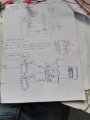
I'm designing a 60V smps for my CNC milling machine using tl494 ic. I've successfully driven the gate drive transformer which can in turn drives the mosfets and I am able to get 60 upto 70v output from the transformer. I'll do rectification and filtering.
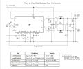
I'm doing it step by step and its voltage regulation time. I have read about error plofiers in the datasheet and I came across with this circuit where 4.92v is given to pin 1 of the tl494 which is the non inverting pin.

My question is,
1. what is the maximum voltage that you can give to the error amplifier input pins?
2. Can you give me a hint on how to regulate 60v dc?
 

Attachments

Alec_t

Joined Sep 17, 2013
14,313
Welcome to AAC!
Hint: Always check the datasheets of components you want to use.
The datasheet tells you the absolute maximum is Vcc+0.3V. Recommended maximum is Vcc-2V.
Use a voltage divider to reduce the 60V to something below the maximum to drive the Vin- input of an error amplifier. If you use the IC's Ref pin, that provides a 5V reference for the Vin+ input of the error amplifier. The voltage divider would then need to divide by 60/5 = 12.
 

Dodgydave

Joined Jun 22, 2012
11,302
The ref pin 14 gives out a 5V precision supply, it's used to provide a fixed voltage on the error amps , pins 1,2 your circuit uses pin 2 as reference and it's set to 5V the output voltage is compared to this by the two resistors 22K, 4.7K across the output supply, so when pin 1 gets to 5V, the error amps limit the pwm.

So you can use any combination of resistance to change the output voltage , or alter the reference on pin 1, . For 60V use a 10K and a 110K resistor on pin 1.
 
Last edited:

Irving

Joined Jan 30, 2016
3,880
What output current are you aiming for? Stepper motors are likely to take several amps so the design of the output transformer to handle that current without saturating will be critical, along with lots of capacitive smoothing with low ESR parts to handle the peak current demands. You will get significant losses in the the output diodes; ideally you should be using synchronous rectification which deploys MOSFETs rather than diodes for efficiency. The TL494 is a very old & dated design and doesn't support synchronous rectification - there are better ICs than that.

If it's not a rude question, other than the educational value, why? A 60v 10A SMPS for CNC machine use can be picked up for as little as 40GBP or 55USD...
 

Thread Starter

greatmebratu

Joined Dec 31, 2019
9
Welcome to AAC!
Hint: Always check the datasheets of components you want to use.
The datasheet tells you the absolute maximum is Vcc+0.3V. Recommended maximum is Vcc-2V.
Use a voltage divider to reduce the 60V to something below the maximum to drive the Vin- input of an error amplifier. If you use the IC's Ref pin, that provides a 5V reference for the Vin+ input of the error amplifier. The voltage divider would then need to divide by 60/5 = 12.
Thank you! I've seen the datasheet and I actually got the above circuit from the datasheet where they give 4.92v to the pin 1 of the error amplifier. If 2v is the maximum voltage that can be given to the pin why would they give it 4.92?
 

Thread Starter

greatmebratu

Joined Dec 31, 2019
9
The ref pin 14 gives out a 5V precision supply, it's used to provide a fixed voltage on the error amps , pins 1,2 your circuit uses pin 2 as reference and it's set to 5V the output voltage is compared to this by the two resistors 22K, 4.7K across the output supply, so when pin 1 gets to 5V, the error amps limit the pwm.

So you can use any combination of resistance to change the output voltage , or alter the reference on pin 1, . For 60V use a 10K and a 110K resistor on pin 1.
Thank you for the feedback! I'm new to electronics so from what I understand the opamp always tries to maintain both the inverting and the non inverting pins equal? If one is above the reference voltage it reduces the duty cycle of the pwm?
But I still have 1 question. By using 110k and 10k voltage divider from the 60v output we are giving 5v to the error amplifier pin. But on the datasheet it says 2v is the maximum. So 5v input is not going to destroy the pins?
 

Attachments

Thread Starter

greatmebratu

Joined Dec 31, 2019
9
What output current are you aiming for? Stepper motors are likely to take several amps so the design of the output transformer to handle that current without saturating will be critical, along with lots of capacitive smoothing with low ESR parts to handle the peak current demands. You will get significant losses in the the output diodes; ideally you should be using synchronous rectification which deploys MOSFETs rather than diodes for efficiency. The TL494 is a very old & dated design and doesn't support synchronous rectification - there are better ICs than that.

If it's not a rude question, other than the educational value, why? A 60v 10A SMPS for CNC machine use can be picked up for as little as 40GBP or 55USD...
Thank you!
I am new to electronics and I was reading books and planning to make an induction Furnace for melting cast iron and steel. I've done simple push pull oscillators but the wave form was not that impressive . I've seen on the Internet that someone who made an induction furnace used tl494 chip so I ordered 100 chips. While I was experimenting about the Furnace one of our cnc power supply stopped working. I ordered one from China for as little as 8 USD but while it is still in transit I'm almost in the feedback stage .
The stepper motor needs 5.85 amps. I've used the flyback transformer directly from the previous 60v smps. I have made my own flyback transformer before that and the snubber resistors keep getting very hot after a few seconds. I even used 3 watt 5x100k resistors in parallel but still gets hot. So maybe it has a huge leakage inductance. I'm also using smoothing capacitors from an old atx computer power supplies. I'm also planning to use a fast switching schottky diodes from the sample atx smps. Like for example I've bunch of stps3045cw diodes salvaged from old boards.
 

Alec_t

Joined Sep 17, 2013
14,313
If 2v is the maximum voltage that can be given to the pin why would they give it 4.92?
The max is not 2V, it's Vcc-2V. So if Vcc is 40V (the recommended Vcc max value) then the recommended max input voltage for the error amplifier is 40V-2V = 38V. Presumably the error amplifier doesn't behave properly if you go above that. In practice the input voltage used would be about 5V.
 

Dodgydave

Joined Jun 22, 2012
11,302
Thank you for the feedback! I'm new to electronics so from what I understand the opamp always tries to maintain both the inverting and the non inverting pins equal? If one is above the reference voltage it reduces the duty cycle of the pwm?
But I still have 1 question. By using 110k and 10k voltage divider from the 60v output we are giving 5v to the error amplifier pin. But on the datasheet it says 2v is the maximum. So 5v input is not going to destroy the pins?
It's Vcc -2V , so the maximum supply is 40V, so that is 38V input voltage to the error amps.
Have you got a circuit diagram ready, or are you using the datasheet one?
 
Top