Facebook
 Google
 GitHub
 Linkedin
http://geekcircuits.com/2010/07/class-d-amp-using-tl494-dc-to-dc-converter-chip-2/
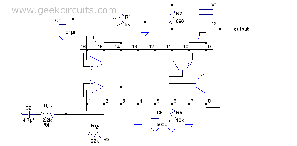
TL494 Audio amplifier
I made this scheme and worked very well:
I do not have the MOS driver IC from the following schema:
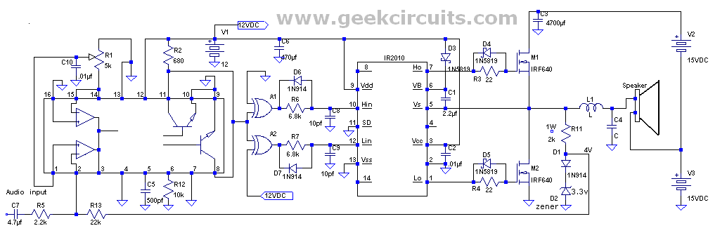
I do not have the IR2010 or any closer.
What to use?
I can use transistors MOSFET (N-MOS, IRF840) or bipolar.
Create the driver from discrete components?
Or try transformer for Gate drive?
Anyway, I need dead time what is done by group D6 / R6 and D7/R7, D4/R3, D5/R4.
For D6 and D7 I have neither the equivalent.
I have 1n4007 but it's not a fast diode.
How to do ? B-E diode of a transistor is good instead of fast diode?
TL494 Audio amplifier
I made this scheme and worked very well:
I do not have the MOS driver IC from the following schema:
I do not have the IR2010 or any closer.
What to use?
I can use transistors MOSFET (N-MOS, IRF840) or bipolar.
Create the driver from discrete components?
Or try transformer for Gate drive?
Anyway, I need dead time what is done by group D6 / R6 and D7/R7, D4/R3, D5/R4.
For D6 and D7 I have neither the equivalent.
I have 1n4007 but it's not a fast diode.
How to do ? B-E diode of a transistor is good instead of fast diode?


")