TL431 programming / resistor values help. I understand but...

Thread Starter

bigjoncoop

Joined Feb 1, 2019
189
Hey fella's,

Main Question:
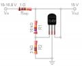
If a TL431 is set/programmed with a voltage divider how does that work when the circuit is being powered from a battery since the voltage is constantly decreasing which would change the value of the voltage divider correct?

Long version:
So recently I've been seeing a lot of circuits that have to do with batteries etc... using the TL431 or similar...

From my research I've gathered that the TL431 can be thought of as an adjustable / programmable zener diode. And by creating a voltage divider will determine/set the value.

I understand all that and I've got it to work on a breadboard. I can set the voltage divider to have the TL431 to conduct or not So I understand how to set it and how it works.

But what I do not understand is how the TL431 is being used when it's in a circuit powered by a battery because -

If I use a voltage divider calculator and the input voltage is let's say 12v and I want 10v on the voltage divider I used two resistors of a certain value. But if the circuit is powered from a battery and that voltage is constantly changing and getting lower then my voltage divider value is also constantly changing...

So how do you set a TL431 with a voltage divider connected to a battery and the output of the voltage divider is always changing as the battery voltage decreases?
 

crutschow

Joined Mar 14, 2008
34,432
So how do you set a TL431 with a voltage divider connected to a battery and the output of the voltage divider is always changing as the battery voltage decreases?
The voltage divider is not connected to the battery (look at the data sheet examples).

The TL431 acts like a Zener (shunt regulator) so you need to have an addition resistor from the battery to the cathode of the device as you would with a Zener.
It then maintains the voltage at the cathode at a constant voltage as the battery voltage varies.

LTspice simulation of example circuit below for a battery voltage (green trace) varying from 4V to 12V:
The LT431 adjusts its cathode current so that the voltage at the Ref Input it keep at a constant 2.5V (red trace).
So you determine the cathode voltage you want and select the resistive divider for 2.5V at the desired voltage.
For two equal value divider resistors, as in the simulation, the output voltage (yellow trace) will then be 5V.

Some of the applications use the TL431 as a comparator and not a Zener (circuit on right).
In that case the divider is connected to the battery and the TL431 turns on (conducts. blue trace) when the Ref input exceeds 2.5V.


Make sense?

1613761550357.png
 
Last edited:

Thread Starter

bigjoncoop

Joined Feb 1, 2019
189
@crutschow

Thanks for your explanation. I sort of understand enough to be able to make it work. I just don't understand the exact reason why...

But from what I gathered I need to make the voltage divider come out to as close to 2.5 volts as possible. So this is what I've came up with... I need the TL431 to turn off/ go open circuit @15v or so:

received_2280019398809787.jpeg
Is that correct to do what I'm looking for?

THX again for your time and help
 

Attachments

crutschow

Joined Mar 14, 2008
34,432
I sort of understand enough to be able to make it work. I just don't understand the exact reason why...
The TL431 has a built-in reference voltage of 2.5V which is connected to one input of a differential amp.
The other amp input is connected to the Ref input.
The diff amp output is connected to the cathode terminal.

So when the Ref voltage is above 2.5V, the differential amp turns on, causing the cathode to conduct current to the anode, and when it is below 2.5V the differential amp turns off, shutting off the cathode current.
I need the TL431 to turn off/ go open circuit @15v or so:
That's ambiguous.
Do you want it off when above 15V or below 15V?
The circuit shown will turn off when it's below 15V.
 

sparky 1

Joined Nov 3, 2018
757
The TL431 has many applications like the zener diode that is adjustable. The TI data sheet reads:
9 Detailed Description
9.1 Overview This standard device has proven ubiquity and versatility across a wide range of applications, ranging from power to signal path. This is due to it's key components containing an accurate voltage reference & opamp, which are very fundamental analog building blocks. TL43xx is used in conjunction with it's key components to behave as a single voltage reference, error amplifier, voltage clamp or comparator with integrated reference.

The integrated circuit is referenced by the intenal voltage reference.
The TL431 is really a three-terminal adjustable precision shunt voltage regulator integrated circuit that showed promise in 1977.

image_2021-02-22_204308.png

Circuits can resemble zener diodes circuit like below for battery.


TL431 series current.JPG
 
Last edited:

Thread Starter

bigjoncoop

Joined Feb 1, 2019
189
@crutschow

Yeah below. It's going to be for a automatic battery discharger to bring it down to storage voltage. I posted a question last week on the topic about some commercially available products that have super simple circuitry and I assumed was a tl431 or a zener diode and a couple people confirm that it's a tl431. I posted images below.

Okay, so the circuit I posted up above is accurate? It'll cut the voltage off when it drops below around 15 volts? Slowly but surely I'll figure out exactly how and why it works the way it does but for the time being I can start using the circuit.

Here is the complete circuit I plan on using same as above just adding a discharge resistor
received_2280019398809787.jpeg

Tonight I'll throw it together on a breadboard and start testing it at different voltages before I start attaching it to $30+ batteries.

Also the tl431 has a max current of 100mA correct? I know I can use it to control a mosfet also if I want to increase the current to discharge the battery any quicker... then I got to worry about heat dissipation etc...

Thanks again @crutschow

Below is the circuit I'm trying to replicate. I just did not add the LED in my schematic. These boards are just connected to the bottom side of a PCB Mount xt60 connector.

P1010040-2_1088x1088.jpgreceived_239428057720991.jpegP1010020-2_1056x1056.jpgBatDisCh_1.jpg
 

crutschow

Joined Mar 14, 2008
34,432
It'll cut the voltage off when it drops below around 15 volts?
The values of 3k and 16k for R3 and R2 will give a cutoff voltage of about 15.9V.
For 15V change R2 to 15k.

Here's an easy way to calculate the resistor values:
We know that the voltage at the TL431 Ref input is 2.5V at the trip point, thus the current through the 3k resistor is 2.5V / 3k = 0.8333mA.
We want 15V at the top of R2 which means it must carry the same current as R3 at that voltage (since the Ref input's current is very small).
R2's value is thus (15V-2.5V) / 0.8333ma = 12.5V / 0.8333ma =15kΩ.
 
Last edited:
Top