Facebook
 Google
 GitHub
 Linkedin
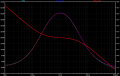
Hello Everyone! I'm very new to the world of power electronics, and have been teaching myself the basics recently as I've been reading through Christophe basso's Spice Simulation book. I'm also new to the site, so I hope this is the proper form for this question. In Basso's book I just got to the section concerning feedback using the TL431. While I understand the derivation for the equations just fine, I've been unable to get the proper response in LTspice for a type 2 compensator. I've tried various different models for the TL431, and for some reason I can't seem to get the response to match the op amp based circuit, or the theoretical TL431 circuit. I've also tried different optocouplers as well. Any ideas as to what is wrong?
Attachments
-
5.7 KB Views: 9
-
1.2 KB Views: 4
-
623 bytes Views: 5
-
300 bytes Views: 2
-
615 bytes Views: 3
-
309 bytes Views: 2
-
524 bytes Views: 4
-
 59 KB Views: 38
 -
 41 KB Views: 42