TL431 Constant Current Source

Thread Starter

reynolds087

Joined Jul 22, 2020
38
Hi Everyone,
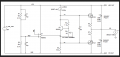
I'm trying to build a current source using a TL431, but I can't figure out how to accurately control the current independently of the input voltage to the system. The use case for this current source is a rail splitting circuit, and I want it to work with a wide range of voltages (5v - 36v). Is there any way to make a more accurate current source that isn't dependent on the input voltage?
 

Attachments

panic mode

Joined Oct 10, 2011
2,715
post your test scenario and resulting data. what kind of error you get and what is it that you expect?

in your circuit one of the variables is current through TL431 itself. you can reduce that by using ATL431 or eliminate it by placing load in the collector rather than emitter of the the transistor.
1642707234886.png
 
Last edited:

Thread Starter

reynolds087

Joined Jul 22, 2020
38
I'll try to use a current sink instead of a source. I am working from a schematic I found online that uses an LM334 as the current source, and was trying to replace that component with parts I have at home. I'll attach the schematic for reference.
 

Attachments

Ian0

Joined Aug 7, 2020
9,667
If you need a source not a sink, then try the LM385 - it works like a TL431 but attached to the positive rail instead of the negative.
 

crutschow

Joined Mar 14, 2008
34,281
Here's the LTspice simulation of a simple 2-transistor current-source that varies a little less than a half mA for a voltage change from 5V to 36V.
That likely would be acceptable for the splitter circuit you posted.
Note the R1 goes to circuit ground and R2 is the circuit load.

1642713650013.png
 
Last edited:

Thread Starter

reynolds087

Joined Jul 22, 2020
38
Here's the LTspice simulation of a simple 2-transistor current-source that varies a little less than a half mA for a voltage change from 5V to 36V.
That likely would be acceptable for the splitter circuit you posted.
Note the R1 goes to circuit ground and R2 is the circuit load.

View attachment 258322
Thank you! Is this a current mirror circuit? It makes sense for the most part, but it has me curious how you selected R1 and R3. Those are the two components that set the current? Or is R1 the set resistor and R3 is for stability or something?
 

panic mode

Joined Oct 10, 2011
2,715
no, this is not current mirror. that would use two transistors with matching characteristics and same type.
in this case R3 is used to set current limit (comparable to R2 in your circuit).
R2 is load (comparable to R3+R4 in your circuit)
R1 is bias (comparable to your R1).
 

panic mode

Joined Oct 10, 2011
2,715
at low current Vbe of Q2 is some less than 0.6V. Iout is some 4mA and pretty much the same as current through load R2 and setting resistor R3 (130 Ohm).

so quick and dirty check:
R3 = Vbe/Oout = 0.6V/0.004A = 150Ohm max (130 Ohm makes sense).

it sure works over desired voltage range, but not sure if your requirements will be ok with output current variation of 10%
 

Thread Starter

reynolds087

Joined Jul 22, 2020
38
at low current Vbe of Q2 is some less than 0.6V. Iout is some 4mA and pretty much the same as current through load R2 and setting resistor R3 (130 Ohm).

so quick and dirty check:
R3 = Vbe/Oout = 0.6V/0.004A = 150Ohm max (130 Ohm makes sense).

it sure works over desired voltage range, but not sure if your requirements will be ok with output current variation of 10%
Thanks for explaining it. 10% should be fine for this rail splitter I'm building. Ideally, I'd like to find a way to get +/- 1% without requiring a dedicated IC, but that is just my curiosity talking. I think I can work with what I have.
 

crutschow

Joined Mar 14, 2008
34,281
It does not appear that node in your circuit is particularly sensitive to the actual current.
The constant-current circuit is more to provide a high impedance load at that point (more than a megohm).
 
Last edited:

Thread Starter

reynolds087

Joined Jul 22, 2020
38
I'm seeing a negative coefficient between the input voltage and the current at the load resistor. Did I configure it wrong? I did change the transistors to BC556 because I have those here.

Circuit_1.png
 

crutschow

Joined Mar 14, 2008
34,281
I'm seeing a negative coefficient between the input voltage and the current at the load resistor
It's not negative.
Notice that the absolute value of current is still increasing with voltage.
You just have R3 inverted from mine so it is showing negative current (resistors are polarized. which is why I modified my resistor icon to have a small circle at one end to indicate the positive end for current flow. When you put the cursor over the resistor it will show the positive current flow direction ).

To get positive current, just reverse the resistor connections.
 

crutschow

Joined Mar 14, 2008
34,281
If you need a source not a sink, then try the LM385 - it works like a TL431 but attached to the positive rail instead of the negative.
Odd think happened.
I downloaded the LM385 Pspice model from TI and put it in LTspice.
At first it seemed to be working, but then I noticed that it is operating the same as the TL431, which has the internal reference voltage going to the anode connection.
It does not go to the cathode as the LM385 data sheet shows.
Seems to be a serious mistake with the TI model.
 

Ian0

Joined Aug 7, 2020
9,667
It has to be small enough to supply the base current to Q1 at the nominal constant-current level at minimum supply voltage and minimum transistor current gain (beta).
I then picked a value somewhat smaller than that.
If Q1 is a MOSFET, then R1 can be very large.
 

Ian0

Joined Aug 7, 2020
9,667
Is there a way to do this with two mosfets instead of two BJTs? I don't have any surface mount PNPs, but I have surface mount N and P channel mosfets.
Yes, you can replace both transistors with MOSFETS, but. . .
Vgs is quite a variable parameter, whereas Vbe doesn't change much. Your constant current would be stable but the actual value would be quite random (±50% of your calculated value) because of the spread in Vgs between different transistors.
OK if you're just making the one, but if you were putting it into prodution - not so great!
 
Top