Hello !
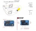
I'm an artist and VERY begginer with circuits and electronics. I'm trying to do a little machine in which a DC motor reductor unravels and then spins a yo-yo back up. Getting into ARDUINOs is a little bit to far for me, so I kind of want to do it with what I got, which are Timer-relays (at the moment I have 1 with three buttons and 1 with 4 buttons that accomodates for a trigger, I'll attach pictures below) and a DC motor. The idea is to have 1 timer connected +- to the motor, and the other one in the opposite polarity.
Every X amount of time
- timerA starts and the motor unravels the yoyo
- there's some waiting time to ensure there are not short circuits
- timerB starts rolling up the yoyo
- there's some waiting time to ensure there are not short circuits
and so on and so forth.
I'll show you my circuit idea where i think the times are too tight and will short circuit. How do I add that delay time? My new idea was to kind of use one timer as the trigger for the other BUT I don't think itll work because 1. Im not sure if the timer on-off signal counts as a switch, and 2. the signal on from timerA will trigger the on from timerB.
I was thinking of how to get a Resting state in which timerB is 'dormant for a 999 amount ', then every X amount of time, timerA turns on, then off, starts timerB in off which then turns on, and then dormant for 999 amount.
or every X amount of time, timerA turns on, then off, theres a delay for which timerB turns on and then off for 999 or until the cycle repeats.
That way they wont ever cross turns off for timerB. Maybe I'll need another timer or a relay but I'm clueless!
Thanks for reading, and sorry for the terrible graphics, its what works for me at the moment ! Ill get any help I can get !!


