It uses 1 LM555 and two CD4066B's. I had to use a separate CD4066 to provide a "hold" function. The 4066's select an R value that, when combined with CT, provide approximate times of 1, 2 and 3 seconds. If more that one button is pressed, only the first button selects the corresponding time setting. Once the timer starts, a 40066 switch disables the button inputs, and the timer runs to completion. After time runs, the button inputs are then re-enabled. Probably could replace the transistors with inverters from a CD40106 Schmitt hex inverter. I haven't tested this on a breadboard yet.
eetech00 you are a star, I wouldn't know how to thank you.
WOW, when I started this project I did not believe it would need so many components! I will have to make 12 of those (there are 12 racers)!!!!
If the timing differences among the outputs you want is directly proportional to the distances among the switches, then one retriggerable monostable can do everything. If, for example, the times between S1 and S2 and between S2 and S3 are 1.0 s, and the monostable is set to 1.1 s, then the three times would be
3.1 s
2.1 s
1.1 s
In other words, depending on what the three times are, it might be possible to have the three switches in series fire only one timing circuit. SO - what are the three times?
Add up all of the component pins. This is the minimum number of soldered connections, and is a good way to judge the relative complexity of two designs you are going to build by hand. Of course, all of this can be done with one $1, 8-pin PIC and one capacitor - if you have a development system, a compiler you are familiar with, know C++, etc.
If the timing differences among the outputs you want is directly proportional to the distances among the switches, then one retriggerable monostable can do everything. If, for example, the times between S1 and S2 and between S2 and S3 are 1.0 s, and the monostable is set to 1.1 s, then the three times would be
3.1 s
2.1 s
1.1 s
In other words, depending on what the three times are, it might be possible to have the three switches in series fire only one timing circuit. SO - what are the three times?
ak
Except the OP doesn't want it to be re-triggerable. Once the timer starts, time must run to completion, ignoring any triggers. Also, I agree that an PIC or similar would be the lowest part count.
I know. I'm just pointing out a possibility he might not have thought through. The physical placement of the switches makes them mutually exclusive,which opens up other logical combinations and solutions.
From what I remember of the old horse racing game, the ball would roll off a flapper and run for about 3-seconds if the ball hits the best hole, 2-seconds if it hits the medium hole to the 1-second if it hits the 3rd best hole.
I don't remember them cascading and hitting all three switches. If a best ball must hit all three switches as it rolls out and each one clicks 1-second, then all timers can be the same (one second) - assuming it take a second for the ball to roll from switch one to switch two.
I think the OP needs to give a clearer description how it works.
If a best ball must hit all three switches as it rolls out and each one clicks 1-second, then all timers can be the same (one second) - assuming it take a second for the ball to roll from switch one to switch two.
From what I remember of the old horse racing game, the ball would roll off a flapper and run for about 3-seconds if the ball hits the best hole, 2-seconds if it hits the medium hole to the 1-second if it hits the 3rd best hole.
I don't remember them cascading and hitting all three switches. If a best ball must hit all three switches as it rolls out and each one clicks 1-second, then all timers can be the same (one second) - assuming it take a second for the ball to roll from switch one to switch two.
I think the OP needs to give a clearer description how it works.
I am trying to built a timer circuit which will have 3 momentary push buttons that each will trigger a timer with 3 different preset durations in the range of 0-4 seconds. Once triggered the timer's output should go high until the timer runs out and any further triggering while the timer is running should be ignored. Then it should return in the idle state, waiting for the next trigger. 555 with RC network accuracy is sufficient (no need to use crystals).
This seams to be exactly what I need, just missing the multiple triggers. Any thoughts on whether they could be implemented, preferably by using 3 sets of RC networks rather than 3 timers?
First of all let me thank everyone for the latest inputs. Also to apologize a million times for my absence since December 22nd. Decided to go to my parents cabin for Christmas, but the weather had different plans for my return trip. 60cm of snow in one night (that is a lot for Greece, even for a mountainous area). Trapped for 12 days, no internet connection but the most beautiful Christmas of my life.
Anyway, happy New Year to everyone!
I cannot believe there was so much going on on my thread while I was away... Also don't know where to start from... so let me try...
1. In any occasion that more than one switch is triggered, the time in between cannot be utilized. It is just too short.
2. There is just one output with three different possible pulse lengths. Not 3 different outputs.
3. EM Fields, thanks for the input. I would greatly appreciate a clearer image as I cannot figure out the diagram especially on the 3x555 version.
4. Any second opinions on whether I should go for eetech00's latest version or EM Fields' design (i.e advantages of each case)?
Thanks a lot to all of you guys, I think I getting closer on this one thanks to you!
EM Fields, thanks for the input. I would greatly appreciate a clearer image as I cannot figure out the diagram especially on the 3x555 version. [/QUOTE]
Here ya go...
The switches are color-keyed to the image you posted of the game, with RED giving the most advancement of the horse, and yellow the least.
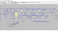
Here's the single 555 version, with circuit descriptions to follow:
Both version started out as LTspice schematics which I edited with PAINT in order to show the real-life switches and to generally tighten things up.
Unless I screwed something up, the plots should still be valid
 Facebook
 Google
 GitHub
 Linkedin

")


