timer circuit with relay output

ebeowulf17

Joined Aug 12, 2014
3,307
ebeowulf17, you seem to have a handle on this. I'll try to clarify a few things. Accuracy is not important. The ability to adjust the timings would be a good thing. Probably would be a 12v DC power source and relay, but that can change.
For those that insist on the purpose I can only say that I don't see the need to disclose the purpose of this circuit. All the information needed has been posted. If you have a specific question/clarification please feel free to ask. Thanks.
I'll probably try to figure out my 555 timer issue this weekend, or just replace it with a counter based timer. I'll let you know if I get it working.

In the meantime, AnalogKid really, really knows his stuff. I guarantee that, now that your design requirements are pretty clearly laid out, any circuit he designs will be better than what I've been working on. I look forward to seeing his approach. (be sure to answer his follow up questions!)
 

Thread Starter

pavo real

Joined Aug 2, 2017
10
Of course everything can be done inside a 41, 8-pin PIC, but where's the fun?

I'm not a big fan of long RC timers, but 1 "accuracy is not important" minute should be fairly repeatable. For 1 hour, use a counter. To keep the output in the ON state after one hour of continuous input pluses has elapsed, stay ON if the input pulses then stop coming, and have a manual reset, you need at least one set-reset flipflop.

1 - CD4060 - 1 hour timer circuit
1 - CD4093 -
2 gates - Output latch/manual output reset
1 gate - 1-minute boxcar timer
1 gate - input signal conditioning.
1 - MOSFET relay driver

Does the switched load run off the same 12 V supply and ground?
If so, what is the peak load current?
If not, what are the voltage and current of the load?

ak
The load would be a solenoid to close a valve. 12v is typical, generally nothing lower. Apparently there also pulse type valves of which I was unaware. That is also a possibility, pulse open/close. What is the 41, 8-pin PIC you mentioned? Thanks.
 

ebeowulf17

Joined Aug 12, 2014
3,307
I just did some reading up on CD4060s. Why in the world didn't I do that sooner? They seem pretty awesome. I never *needed* one before, and they have so many more pins than a 555, but now that I've got the basic idea of how they work, they seem way better for any kind of timer circuit. Live and learn!

I'll definitely be replacing the 555 with a 4060 when I revisit this circuit.
 

AnalogKid

Joined Aug 1, 2013
12,174
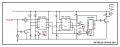
First pass. I love the CD4093, but the logic polarity didn't work out. It would have taken at least 5 gates. With a NOR gate it takes only 3 to do the control logic stuff.

R1-C1-U1A is the 1-minute timer.

U1B and R4 help create hysteresis at the U1A input to prevent the slow-rising voltage from creating a noise burst as it crosses the CMOS transition level. One of the big mistakes in 1960's DTL and TTL is that there was no hysteretic NOR gate. That miss carried through to CMOS. Grrrr.

Input pulses less than 1 minute apart keep C1 charged up high enough to make a logic high level at the inputs to U1A and U1C. Normally this makes a low at the 4060 input, allowing it to count. If the input pulses are too far apart, U1A goes low. This propagates through to a high at the 4060 reset input, holding the counter at all 0 outputs.

If the counter runs for an entire hour, U1-Q14 goes high. This turns on the relay driver, and forces a high into the timing circuit through D2. This acts as a counter inhibit. A high at U1C-pin 9 forces its output low and prevents any reset signals from the input stage. In this way, the counter is latched; Q14 will stay high forever or until the reset button is pressed.

The CD4060 is a 14 bit counter, which means that the period of the output waveform at Q14 is 16,384 times longer than the period of the oscillator (formula in the datasheet). Since we want Q14 to sit low for 1 hour, the total Q14 period is 2 hours, 7200 seconds. In theory, Q14 will go high and latch the counter in 1 hour, 4 seconds with the component values shown.

This is a simple circuit based on very little information, and thus has possible issues. First, the input is level sensitive, not edge sensitive. If the input is held high indefinitely, the counter will run out the 1-hour interval even though the input is not changing. We don't know if the input can be trusted not to do this. This can be improved by using the unused U1D to add a differentiator (edge detector) to the input if needed. Second, the reset button does not reset the input. Depending on the logic level at U1 pin 8 when the reset button is released, the counter will either start counting immediately or wait for the next input pulse.

Apologies for the ratty looking schematic; the PDF converter is having a bad day. R2 is 90.9 K.

ak
PulseEn1HrDelay-1-c.gif
 

Attachments

Last edited:

EM Fields

Joined Jun 8, 2016
578
I am not the most experienced, so please bear with me. I am looking for a circuit to start timer with a pulse. New pulses would be ignored. After one minute of no pulse, then reset timer and wait to start. After one hour of pulse(s), then a high output to relay.
If I'm correctly interpreting what you're asking for, this appears to do what you want:
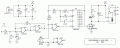
555 pulse train detector.png
 
Last edited:

Thread Starter

pavo real

Joined Aug 2, 2017
10
First pass. I love the CD4093, but the logic polarity didn't work out. It would have taken at least 5 gates. With a NOR gate it takes only 3 to do the control logic stuff.

R1-C1-U1A is the 1-minute timer.

U1B and R4 help create hysteresis at the U1A input to prevent the slow-rising voltage from creating a noise burst as it crosses the CMOS transition level. One of the big mistakes in 1960's DTL and TTL is that there was no hysteretic NOR gate. That miss carried through to CMOS. Grrrr.

Input pulses less than 1 minute apart keep C1 charged up high enough to make a logic high level at the inputs to U1A and U1C. Normally this makes a low at the 4060 input, allowing it to count. If the input pulses are too far apart, U1A goes low. This propagates through to a high at the 4060 reset input, holding the counter at all 0 outputs.

If the counter runs for an entire hour, U1-Q14 goes high. This turns on the relay driver, and forces a high into the timing circuit through D2. This acts as a counter inhibit. A high at U1C-pin 9 forces its output low and prevents any reset signals from the input stage. In this way, the counter is latched; Q14 will stay high forever or until the reset button is pressed.

The CD4060 is a 14 bit counter, which means that the period of the output waveform at Q14 is 16,384 times longer than the period of the oscillator (formula in the datasheet). Since we want Q14 to sit low for 1 hour, the total Q14 period is 2 hours, 7200 seconds. In theory, Q14 will go high and latch the counter in 1 hour, 4 seconds with the component values shown.

This is a simple circuit based on very little information, and thus has possible issues. First, the input is level sensitive, not edge sensitive. If the input is held high indefinitely, the counter will run out the 1-hour interval even though the input is not changing. We don't know if the input can be trusted not to do this. This can be improved by using the unused U1D to add a differentiator (edge detector) to the input if needed. Second, the reset button does not reset the input. Depending on the logic level at U1 pin 8 when the reset button is released, the counter will either start counting immediately or wait for the next input pulse.

Apologies for the ratty looking schematic; the PDF converter is having a bad day.

ak
View attachment 132298
NICE! Thanks. I will plan to build this and see how it works. May need some help with the pulse/trigger.
 

eetech00

Joined Jun 8, 2013
4,709
First pass. I love the CD4093, but the logic polarity didn't work out. It would have taken at least 5 gates. With a NOR gate it takes only 3 to do the control logic stuff.

R1-C1-U1A is the 1-minute timer.

U1B and R4 help create hysteresis at the U1A input to prevent the slow-rising voltage from creating a noise burst as it crosses the CMOS transition level. One of the big mistakes in 1960's DTL and TTL is that there was no hysteretic NOR gate. That miss carried through to CMOS. Grrrr.

Input pulses less than 1 minute apart keep C1 charged up high enough to make a logic high level at the inputs to U1A and U1C. Normally this makes a low at the 4060 input, allowing it to count. If the input pulses are too far apart, U1A goes low. This propagates through to a high at the 4060 reset input, holding the counter at all 0 outputs.

If the counter runs for an entire hour, U1-Q14 goes high. This turns on the relay driver, and forces a high into the timing circuit through D2. This acts as a counter inhibit. A high at U1C-pin 9 forces its output low and prevents any reset signals from the input stage. In this way, the counter is latched; Q14 will stay high forever or until the reset button is pressed.

The CD4060 is a 14 bit counter, which means that the period of the output waveform at Q14 is 16,384 times longer than the period of the oscillator (formula in the datasheet). Since we want Q14 to sit low for 1 hour, the total Q14 period is 2 hours, 7200 seconds. In theory, Q14 will go high and latch the counter in 1 hour, 4 seconds with the component values shown.

This is a simple circuit based on very little information, and thus has possible issues. First, the input is level sensitive, not edge sensitive. If the input is held high indefinitely, the counter will run out the 1-hour interval even though the input is not changing. We don't know if the input can be trusted not to do this. This can be improved by using the unused U1D to add a differentiator (edge detector) to the input if needed. Second, the reset button does not reset the input. Depending on the logic level at U1 pin 8 when the reset button is released, the counter will either start counting immediately or wait for the next input pulse.

Apologies for the ratty looking schematic; the PDF converter is having a bad day.

ak
View attachment 132298
HI ak

Using the RC timing values you specified I think you meant to use Q4 output instead of Q14 output.

eT
 

AnalogKid

Joined Aug 1, 2013
12,174
Or (I just noticed this), are you suggesting I meant to connect the output stage to Q4 because that is nearest to the output transistor gate?

ak
 

AnalogKid

Joined Aug 1, 2013
12,174
Now that ee and I have had our little thing, here is something for the TS. This is the math behind selecting the CD4060 oscillator components.

The CD4060 makes an excellent long-range timer or monostable. It doesn't have an oscillator enable/disable input nor a carry output, so you have to get creative. I've used the diode-disable trick many times.

From the CD4060 datasheet, the oscillator frequency f(osc) = 1 / (2.2 x R x C)
Therefore, the oscillator period t(osc) = 2.2 x R x C.

Each counter stage divides its input frequency by two, which is the same as multiplying its period by two.

The divided output wants to be low for 1 hour. Because that is only the first half of one complete output cycle, the output period (tout) = 2 hours = 7200 seconds.

7200 / 16384 (which is 2 to the 14th) = 0.439453
This is T(osc), the oscillator period, and ideally equals 2.2 x R x C.

I started with R = 100K, and fished around until I had an R-C combination close to the target period.

t(osc) = 2.2 x R x C = 2.2 x 90,900 x 2.2^-6 = 0.439956 seconds.

t(out) = 0.439956 x 16,384 (2^14) = 7208.24 seconds. Therefore the output delay before the relay energizes is 1 hour 4 seconds.

ak
 

ebeowulf17

Joined Aug 12, 2014
3,307
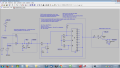
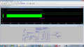
As I expected, AnalogKid came up with a great circuit, cleaner than anything I could do. Nevertheless, just for my own experience, I decided to continue working and see what I could do on my own. Along the way I learned a lot about the CD4060 (no prior experience with it, but I'm glad I've gotten to know it now) and also a lot about LTspice (there were some snags in getting the CD4060 simulations working properly.)

I'm not sure that posting this here really adds anything to the conversation, since there's already a great solution on the table, but I'm proud that I was able to make it work, so I'm going to share it anyway!

The input stage would probably need to be adjusted based on the nature of the pulses, and the output stage could be varied any number of ways depending on relay specs, but those are the easy parts. Getting the timing, resetting, and latching behaviors working right were the fun & interesting parts.

pulses-for-hour_14_schematic.png pulses-for-hour_14_output.png
 

Attachments

Top