Facebook
 Google
 GitHub
 Linkedin
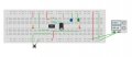
... OKThose look correct to me. All we are doing is cascading two timers each configured as a 555 One Shot so the first timer is triggered, creates a time delay and then the second timer is triggered. 555 timer Mono stable (one shot) circuit gives a good example of what we are doing. A single momentary button press starts the process going in this case. Timing is controlled by the values of the timing resistor / Capacitor (RC Network) on pins 6&7 joined.
Ron
But it doesn't seem to do what I want it to do as per OP
Do you think the circuits.io isn't running it right?
")