Time on/off delay

Thread Starter

inwo

Joined Nov 7, 2013
2,419
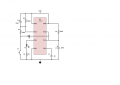
Came up with what I think is a minimum component dual timer.
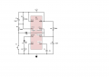
Integrated trigger and time delay off.
It's a solution for/from another thread.

As I just woke up and drew it out before I forgot, I'm wondering if someone would check for errors?

Low pulses trigger after reaching duty cycle set by R3-C3.
Minimum time on set by R2-C2.
Input low = always on.

D1 keeps C2 low and ready for full delay off cycle.

I don't know if this is unique or I've reinvented the wheel, but it seems to do what I need.
 

Attachments

Thread Starter

inwo

Joined Nov 7, 2013
2,419
Thanks for looking.
Wish I could do that!:)

The schematic sw I use didn't even have a 555. I had to build it.

I see one problem already. The 1MEG will need to be a little larger to let pin 2 get down to 1/3 of supply and trigger reliably. (your helpful label reminded me)

This is for a tank level indicator.
http://forum.allaboutcircuits.com/showthread.php?t=94220
I can't believe on/off timers are so hard to find.

edit:
Don't bother with the math.
Times are immaterial.
Just basic function is fine,
 
Last edited:

#12

Joined Nov 30, 2010
18,224
When power is applied, C3 immediately raises trigger above 1/3 Vcc and that sets the output low (no LED).
When power is applied, pin 6 is low and waiting while R2 starts charging C2 towards 2/3 Vcc, therefore output is high.

Illegal condition. Results undefined, and I haven't even gotten to the switch. We need somebody to simulate this to see if I'm wrong.
 

Thread Starter

inwo

Joined Nov 7, 2013
2,419
When power is applied, (switch open)C3 immediately raises trigger above 1/3 Vcc and that sets the output low (no LED).(yes)
When power is applied,(switch open)pin 6 is low and waiting (yes)while R2 starts charging C2 towards 2/3 Vcc,(can't charge with disch. pin low) therefore output is high.(no)

Illegal condition. Results undefined, and I haven't even gotten to the switch. We need somebody to simulate this to see if I'm wrong.
Yeah, I'm hoping for simulation.

I believe there are 555 gurus on here. If it works, I'd like to no if it's unique. (in a good way)

If it doesn't work, someone can point me to a minimum timer, that does delay on AND delay off, from a low side switch.

This is the only way I can build circuits. Waking up with an inspiration. I never learned how to learn from others.:(

I may get time to build it tomorrow.
Haven't worked with 555s for years, but still have parts. Maybe even a board that I can solder up.

Thanks again.:)
 

#12

Joined Nov 30, 2010
18,224
Slow on and slow off seems like it can be done with a cmos Comparator or op-amp and an RC, which, after all, is what a TL555 is, but containing a bunch of decision makers.
12V, resistor, SPDT switch, capacitor, Schmitt trigger, viola. Am I missing something?
 

Thread Starter

inwo

Joined Nov 7, 2013
2,419
As you say, that's what a 555 timer is.

If someone comes up with a <8 component dual delay with other components, I'll check it out. (not counting switch or indicator)

I started with discrete components. Then thought, why? By the time you get trigger levels, latch, and hysteresis.
 

tracecom

Joined Apr 16, 2010
3,944
The circuit works after a fashion.

Close S1 and hold it closed. After 4 seconds pin 3 goes high. Open S1 and after 4 seconds, pin 3 goes low.

Simply closing S1 and releasing it before pin 3 goes high does nothing. Likewise, holding S1 closed keeps pin 3 high for the duration of the time S1 is closed plus 4 seconds.

I suppose there is a use for the circuit, but it seems more likely to require a toggle switch for S1 than a momentary push button.
 

#12

Joined Nov 30, 2010
18,224
I'm just too busy to really pay attention lately. Go to Off Topic and see my Lucky Day thread. I hope you have something to add to that thread.:)
 

Thread Starter

inwo

Joined Nov 7, 2013
2,419
The circuit works after a fashion.

Close S1 and hold it closed. After 4 seconds pin 3 goes high. Open S1 and after 4 seconds, pin 3 goes low.

Simply closing S1 and releasing it before pin 3 goes high does nothing. Likewise, holding S1 closed keeps pin 3 high for the duration of the time S1 is closed plus 4 seconds.

I suppose there is a use for the circuit, but it seems more likely to require a toggle switch for S1 than a momentary push button.
Hope to get it built later.
The push button will be a level sensor that is either on, off, or bouncing.
From what you say it will work just as wanted.

It will ignore some bounces-on and some bounces off.:)
 

tracecom

Joined Apr 16, 2010
3,944
If someone comes up with a <8 component dual delay with other components, I'll check it out. (not counting switch or indicator)
Don't tell #12, but I can do it with a 50 cent micro-controller and a .1uF cap (not including the switch and indicator.)
 
Top