Facebook
 Google
 GitHub
 Linkedin
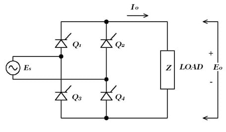
I want to make a variable power supply using a thyristor full wave rectifier bridge into a capacitor filter into some sort of regulator but I'm not totally sure how to go about it, in large part due to the fact I'm new to thyristors and I can't get LTspice to simulate a thyristor model properly.
Can someone give me an example of such a supply? At least the variable rectifier bridge >capacitor part. I would greatly appreciate it.
I intend for the power supply to run at a bit over 2 amps DC with 6 amp AC peaks with an output between 250v and 25v.
Thanks in advance.
Can someone give me an example of such a supply? At least the variable rectifier bridge >capacitor part. I would greatly appreciate it.
I intend for the power supply to run at a bit over 2 amps DC with 6 amp AC peaks with an output between 250v and 25v.
Thanks in advance.