 Facebook
 Google
 GitHub
 Linkedin
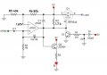
Thank you very much again, I am sorry, I did not have the time to test the previous circuit yet, ill do it tomorrowIn this version on power up Q3 turns ON and holds the output of the LM393 LOW until C2 has sufficiently charged.
C2 can be as large as needed and may not need C1.
View attachment 289488
Thyristor keeps turning on...
- Thread starter Vilius_Zalenas
- Start date


| Thread starter | Similar threads | Forum | Replies | Date |
|---|---|---|---|---|
|
|
Thyristor control under PWM +ZC | Analog & Mixed-Signal Design | 8 | |
|
|
Old thyristor datasheet | Datasheets, Manuals & Parts Identification | 14 | |
|
|
70TPS12 Thyristor - Help! | General Electronics Chat | 38 | |
|
|
LTspice Thyristor and Triac | Power Electronics | 1 | |
| T | Half-wave rectification using a thyristor | Digital Design | 20 |


