Thyristor keeps turning on...

Thread Starter

Vilius_Zalenas

Joined Jul 24, 2022
192
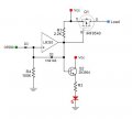
Ohh, sorry, actually, I forgot to connect the MOSFET gate wire. I don't want to delete my previous message not to confuse anyone. That was my mistake. MOSFET turns off as expected, the only problem is that it has the same opened initial state problem. Just like the led...

When I power the circuit on (no overcurrent condition is assumed), I have to mechanically short the LM393 output to ground to turn the led off and turn the MOSFET on, after that, it works perfectly...

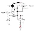
It is strange, because when no overcurrent condition is present, the LM393 output is low, (actually giving around 0.11V) so in other words, I just ground the almost grounded pin, and then circuit starts to operate normally. Would a pull-down resistor solve the problem? (with respect to the R1 and pull-down one ratio)
 

MisterBill2

Joined Jan 23, 2018
27,619
Hi,

I am a beginner HW designer (student at the moment). I have a little circuit involving LM393 comparator and a thyristor that I have to turn under certain conditions...


The idea is that when that condition is met, the LM393 outputs logical one, which should trigger the thyristor (BT169D). I added a simple transistor stage just to make sure the triggering signal for the thyristor gate has enough voltage and current. However, the thyristor turns on right after the supply voltage is applied to the circuit... Have you got any ideas, how could I fix it? Circuit in the attachments.

I made sure my wiring is correct.
The LM393 does not output a high signal right after the power on. LM393 has a default logical zero output state (I verified it with measurements.)

Thank you in advance

View attachment 288857
The NPN stage is a non-inverting emitter follower. A positive signal on the base will certainly give a positive signal from the emitter. It may also be that the default low at the comparator output does not appear until after the high provided by the pull-up resistor has switched on the transistor. So the solution might be to delay the _5 volts to both the comparator pull-up and the transistor collector.
 
Last edited:

ElectricSpidey

Joined Dec 2, 2017
3,336
I know you have moved past using the SCR, and that is a very good thing.

I just ran some sims with a SCR model that I happen to have, and the results are:

When the load is on the anode the SCR works as suspected.
When the load is on the cathode the SCR does indeed stop conducting when the gate voltage is removed.

I can't assume your SCR model will behave the same, but at least now you know you aren't crazy.

1677967650509.png1677967807663.png
 

Thread Starter

Vilius_Zalenas

Joined Jul 24, 2022
192
I know you have moved past using the SCR, and that is a very good thing.

I just ran some sims with a SCR model that I happen to have, and the results are:

When the load is on the anode the SCR works as suspected.
When the load is on the cathode the SCR does indeed stop conducting when the gate voltage is removed.

I can't assume your SCR model will behave the same, but at least now you know you aren't crazy.

View attachment 288923View attachment 288924
Thank you, that will be a perfect lesson for me in the future.
However, now I have to make the last step towards my solution and solve the problem how to make the initial states of the transistor and the led inverted... I guess my LM393 output pull-up resistor does all the nasty things, until the voltage switches all the internal logic to it's real states (by that time, the transistor is already latched :( ) I am trying to think of some RC delay circuit, but for now, I have not found the solution, any ideas?
 

Attachments

ElectricSpidey

Joined Dec 2, 2017
3,336
As I mentioned before your open collector comparator is probably going high for a very short time at start up, something you won't be able to detect with a meter.

I'm sure @sghioto will have a solution for you.

Possibly something as simple as a capacitor from the output to ground.
 

sghioto

Joined Dec 31, 2017
8,634
It could be an initial pulse from the previous stage. Could try a 100nf cap from the + input of the LM393 to ground.
Same as across R4.
And try adding 100nf cap from the output of the LM393 to ground as well.
 

Thread Starter

Vilius_Zalenas

Joined Jul 24, 2022
192
It could be an initial pulse from the previous stage. Could try a 100nf cap from the + input of the LM393 to ground.
Same as across R4.
And try adding 100nf cap from the output of the LM393 to ground as well.
100 nF across R4 did not help, I guess it will the initial pullup resistor thing...
I have also tried 470 uF across R1 and and 470 uF from the LM393 output to ground, it did not work properly (I was not even triggering the overcurrent state)
 

Thread Starter

Vilius_Zalenas

Joined Jul 24, 2022
192
No, don't put any caps across R1 and 470uf is way too large.
By experimenting I found that putting 60-70 nF cap across lm393 output prevents from the initial latch. But the circuit sometimes would not latch at all when the real overcurrent event happens. 60-70 nF is that boundary: sometimes circuit works perfectly, sometimes I get the initial latch, sometimes, it does not latch at overcurrent... I feel like I am really close to the finish, just need to make the circuit stable now...
 

sghioto

Joined Dec 31, 2017
8,634
Do you have any filter caps installed on the 5 volt supply pins of the LM393 and the OP290? This might be the instability problem. I would use at least 10uf caps.
Try disconnecting the connection from D3 to the OP290 to see if the LM393 latches when powered ON. This might tell us where the problem is originating from.
Another mod to try and eliminate the initial latch issue using R2 and C1 assuming it's coming from the OP290.


1677981300799.png
 

MisterBill2

Joined Jan 23, 2018
27,619
I suggest the RC delay should be on the supply side of the pull-up resistor, so that it will only have an effect at power up, which is where the problem is. and the delay does not need to be very long, unless the problem is with the input signals to the LM393.
 

Thread Starter

Vilius_Zalenas

Joined Jul 24, 2022
192
Do you have any filter caps installed on the 5 volt supply pins of the LM393 and the OP290? This might be the instability problem. I would use at least 10uf caps.
Try disconnecting the connection from D3 to the OP290 to see if the LM393 latches when powered ON. This might tell us where the problem is originating from.
Another mod to try and eliminate the initial latch issue using R2 and C1 assuming it's coming from the OP290.


View attachment 288934
I put a 33 uF in parallel with 100 nF to OP290 and LM393 supply. I tried your circuit (R4 was 1.2 MOhm in my case) The circuit was not latching at startup, but it was not latching even when the real overcurrent event ocurred. I guess the problem is with R2... Should I put a cap across R2?

If I remove D3, the circuit does not latch at all
 
Last edited:

sghioto

Joined Dec 31, 2017
8,634
Ok, seems I have solved it, my solution was 1 uF across pull up resistor
What that is doing is delaying the mosfet turning ON which to me indicates the issue was from the OP290.
However that does put a strain on the internal NPN transistor in the LM393 as the 1uf cap does present a brief short circuit.
Try this arrangement with R1 and R2 fixed at 1K each.
1678021130057.png
 

sghioto

Joined Dec 31, 2017
8,634
Looking again at the overall circuit it seems that the first stage of the OP290 can be simplified by removing those four 100K resistors and wiring the opamp as a positive input buffer.
1678022086533.png
 

Thread Starter

Vilius_Zalenas

Joined Jul 24, 2022
192
What that is doing is delaying the mosfet turning ON which to me indicates the issue was from the OP290.
However that does put a strain on the internal NPN transistor in the LM393 as the 1uf cap does present a brief short circuit.
Try this arrangement with R1 and R2 fixed at 1K each.
View attachment 288967
Sadly, the circuit does not latch at all if I put R2 of any value... I guess I will have to deal with it (not putting an R2 at all).
Another thing is that sometimes when I just plug the supply to this circuit and apply the load, the circuit latches for the first time, but after that, I can do as many measurements as I want. I put a maximum of 2.5 uF as C1 (any more capacitance causes the circuit not to latch at all).

I was thinking, is there any circuit configuration, that would do the following:
when I press the button, I want to get a short contact period, then disconnect the circuit (while the button is still pressed) and connect that circuit again for as long, as the button is pressed. (all this should happen in 100-200 ms period.) This way I would eliminate the described effect.

Have you got any circuit on your mind, that would behave as described (using triggers or whatever...)?
 

sghioto

Joined Dec 31, 2017
8,634
Not sure how that would eliminate the circuit from latching on power up.
I think you should revisit my post #30.
The reason it was probably not latching with the over current was the voltage loss through D3 and R2. Readjusting the voltage divider on the minus input should fix the problem.
 

Thread Starter

Vilius_Zalenas

Joined Jul 24, 2022
192
Not sure how that would eliminate the circuit from latching on power up.
I think you should revisit my post #30.
The reason it was probably not latching with the over current was the voltage loss through D3 and R2. Readjusting the voltage divider on the minus input should fix the problem.
For now, my problem is that it latches right after the power is supplied (only for the first time) I have already readjusted the voltage divider (taking into account D3 drop.) The latch up event happens right at 100 mA of current, but the problem is the initial latch up
 

sghioto

Joined Dec 31, 2017
8,634
Let's try something different with this mod on the minus input.
On power up C1 will hold the minus input at 5 volts briefly hopefully keeping the output of the LM393 low and not latching.
C1 can be as large as needed.
1678417306350.png
 
Last edited:

sghioto

Joined Dec 31, 2017
8,634
In this version on power up Q3 turns ON and holds the output of the LM393 LOW until C2 has sufficiently charged.
C2 can be as large as needed and may not need C1.
1678489111142.png
 
Top