This goes to zero?!

Thread Starter

ricebridge

Joined Jun 24, 2017
30
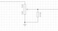
This simple volume controller between a TL074 (used as a buffer) and an LM386N-4… doesn’t work! :eek:
While the volume does indeed rise as I turn it up, it all goes silent once I reach the last fifth or so of the dial. In other words, while some go to 11, mine goes to 0…
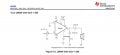
The LM386 is hooked up as shown in the figure from the TI datasheet, although I’ve used a 22μF cap instead of the 250 one and a 100nF instead of the 50nF (0.05 μF) one.
Any suggestions?
 

Attachments

MisterBill2

Joined Jan 23, 2018
27,193
Which circuit are you asking about?? And why the resistor shunting the wiper to common? I see no benefit at all to that addition,except that it may overload the audio signal source.
Also, your volume control may be defective. That does happen.
 

Thread Starter

ricebridge

Joined Jun 24, 2017
30
Which circuit are you asking about?? And why the resistor shunting the wiper to common? I see no benefit at all to that addition,except that it may overload the audio signal source.
Also, your volume control may be defective. That does happen.
The first one. The 2k4 resistor is there to emulate a log pot since I only had lin ones available.
 

MisterBill2

Joined Jan 23, 2018
27,193
Another thought is that there might possibly be some DC level on the audio source, and the LM386 does not like any DC bias on the input. So a coupling capacitor prior to the variable pot would be a solution, if that is the case. A simple DC voltmeter test will tell.
And, still, the pot may have a non-contacting area towards maximum. I have seen that a few times with used parts.
 

Thread Starter

ricebridge

Joined Jun 24, 2017
30
Another thought is that there might possibly be some DC level on the audio source, and the LM386 does not like any DC bias on the input. So a coupling capacitor prior to the variable pot would be a solution, if that is the case. A simple DC voltmeter test will tell.
And, still, the pot may have a non-contacting area towards maximum. I have seen that a few times with used parts.
I have a 1μF cap directly at the input, before the TL074 which goes before the pot. The TL074 is brand new and gets +- 8.5VDC in supply voltage. Could there still be a leak somehow?
 

sghioto

Joined Dec 31, 2017
8,633
I have a 1μF cap directly at the input,
If this cap is polarized the positive end should connect to the output of the TLO74.
Technically since the supply is bipolar there shouldn't be any dc offset on the output of the TLO74.
Post the schematic of the TLO74 circuit please.
 
Last edited:

MisterBill2

Joined Jan 23, 2018
27,193
The reason we ask for the whole circuit is that on many occasions the problem is visible in an area different than where the cause is located. That insight comes from both understanding how things work, and from experience. Primarily from understanding how things work. THAT often comes from experience, AFTER LEARNING how things work. and paying attention also helps.

For the LM386, it does not take a lot of positive bias on the input to cut off the first input transistors. It would not take measurable leakage and a high input resistance to approach cutoff. But a defective pot is also a suspect. If the moving contact loses connection with the resistance you get nothing thru.
 
Last edited:

Thread Starter

ricebridge

Joined Jun 24, 2017
30
The reason we ask for the whole circuit is that on many occasions the problem is visible in an area different than where the cause is located.
Thanks. Well I think that might just be the case here. My new prime suspect is the poor supply voltage to the TL074 (not pictured, comes before the vol pot which in turn goes before the LM386). Measuring what actually comes out from the power supply showed about 8VDC on both sides, a bit lower on the positive side at that.

I read that a TL074 needs at least +-10VDC to perform properly; too bad that that info wasn’t in the datasheet (smh). Moreover, am I right in suspecting that an uneven power supply will cause DC offset…?

So I’ll try that first before uploading the schematic. No big secrets there, it’s just that I have it on another device.
 

atferrari

Joined Jan 6, 2004
5,001
I read that a TL074 needs at least +-10VDC to perform properly; too bad that that info wasn’t in the datasheet (smh).
Please tell and give a link to where you read that.

I used those opamps in my first attempts to understand how they work; my dual PSU was always +-9V.
 

MisterBill2

Joined Jan 23, 2018
27,193
Certainly a non-balanced set of voltages may contribute to a DC offset, and looking at the internal circuit of the LM386 in the National data book, it probably will not like much DC positive bias on either input. So I suggest trying a coupling capacitor between the pot wiper and pin 3 of the LM386.
 

Thread Starter

ricebridge

Joined Jun 24, 2017
30
That circuit in reality would be using the TL074 outside its specifications. Its minimum supply voltage is 9V single supply, or + and - 4.5V with respect to 0V. Only the new TL074H versions would work with a single +5V supply.

smh again. I missed that small detail, it's single supply in that example. blah. my bad.
 

MrAl

Joined Jun 17, 2014
13,667
If this cap is polarized the positive end should connect to the output of the TLO74.
Technically since the supply is bipolar there shouldn't be any dc offset on the output of the TLO74.
Post the schematic of the TLO74 circuit please.
Wouldn't that depend on the circuit, which we have not seen yet?
Op amps always have some DC output offset due to the input offset. How much depends a lot on the gain, which we don't even know yet :)
 
Top