Facebook
 Google
 GitHub
 Linkedin
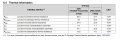
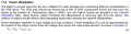
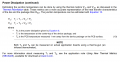
I have some questions regarding thermal calculation for the voltage regulator TPS7A3001DGNT.
\[ P_D = ( V_{IN} - V_{OUT} ) ( I_{MAX}) + (V_{IN} ) ( I_Q) \]
What is \[ I_Q \] in the equation above ?
\[ P_D = ( V_{IN} - V_{OUT} ) ( I_{MAX}) + (V_{IN} ) ( I_Q) \]
What is \[ I_Q \] in the equation above ?