[theoretical design] RGB matrix mixer

Thread Starter

NOISEBOB

Joined Jul 7, 2019
48
Hello...

ages ago i split up a VGA signal and put in some pots to cut and boost the individual color signals, it went something like this:


it did work, but as i was using a variable power supply, i tested my luck and went a bit over 5v and the graphics card blew up. from there i abandoned the project.

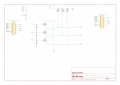
now i want to do it again, only more ambitiously. i want to make a RGB matrix mixer and i am thinking this would do it:


what do you think? is it possible?

i'm thinking it's best just to leave HSYNC and VSYNC alone.

general VGA hacking ideas welcome!
 

Attachments

ronsimpson

Joined Oct 7, 2019
2,989
On both pages you have +5V and ground connected together.
On page 2 you have three 75 ohm resistors in parallel for 25 ohm termination of the VGA connector. Remove two of the resistors. Or make the resistors 220 ohms.
Before fixing the transistors, what is the circuit doing?
It appears that: Rout can be R+G+B or Rout=G or Rout=G/2+B/2. It looks like any output can be any combination of any inputs.
 

Thread Starter

NOISEBOB

Joined Jul 7, 2019
48
On both pages you have +5V and ground connected together.
oops. i have no idea how that happened. silly. fixed

On page 2 you have three 75 ohm resistors in parallel for 25 ohm termination of the VGA connector. Remove two of the resistors. Or make the resistors 220 ohms.
i drew inspiration from this: https://web.archive.org/web/20060112082440/http://www.anatekcorp.com/driving.htm
anatek said:
Notice that the base of the driver circuits’ transistors connect to ground through a 75-ohm resistor. As I mentioned before, this resistance provides the proper amount of load resistance to the PC video card. The base of each monitor’s driver-amplifier connects to this point. the multiple bases connected to this resistor do not alter the 75-ohm termination resistance, appreciably, allowing multiple emitter-followers to be driven from the video card. In turn, this feature is what allows the PC video card to drive multiple monitors.
would you say that that is a mistake?


Before fixing the transistors, what is the circuit doing?
oh.. seems i also put in NPN transistors, where there should be PNP. it is fixed.

It appears that: Rout can be R+G+B or Rout=G or Rout=G/2+B/2. It looks like any output can be any combination of any inputs.
that is the intention, exactly.

here's the updated schematic:
 

ronsimpson

Joined Oct 7, 2019
2,989
Next-1: If RV1 is turned to zero ohms, then Q?-Emitter is shorted to +5V and the transistor will burn out.
Next-2: The three transistors have their emitters connected together. This will not cause a "mixing" if the three signals. It will cause the strongest (most positive) to drive the output. The smallest signal will not be in the output.
I think to get the three signals to add or mix you need a circuit that looks like a audio mixer.
1571678546850.png
 
Top