There are 5 tubes. 3 UX-224 tetrode RF amplifiers in the tuner chassis. A UX-245 triode Audio amplifier and UX-240 diode for the DC in the power chassis.
No. North American AM radio stations are only 10kHz apart. Then to avoid hearing 2 adjacent stations at the same time, their audio must be steeply cut below 5kHz, 3.5kHz can still be heard but nothing higher. Some modern AM stations apply pre-emphasis (treble boost) between 3kHz and 4kHz.
Radioworld.com says, "The result is that an “above average” receiver today has audio response that is less than 4.5 kHz. In fact most have audio response that is down 10-12 dB at 5 kHz – and the rolloff can start at around 2 kHz.
No. North American AM radio stations are only 10kHz apart. Then to avoid hearing 2 adjacent stations at the same time, their audio must be steeply cut below 5kHz, 3.5kHz can still be heard but nothing higher. Some modern AM stations apply pre-emphasis (treble boost) between 3kHz and 4kHz.
Radioworld.com says, "The result is that an “above average” receiver today has audio response that is less than 4.5 kHz. In fact most have audio response that is down 10-12 dB at 5 kHz – and the rolloff can start at around 2 kHz.
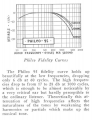
Very well, I retract what I said and we must consider harmonics too which are present in music, the piccolo is one of the higher frequency instruments it seems, around 5KHz. This agrees with what you're saying too and its from the 1930s:
Gotta love radio, it was how I got interested in electronics back in 1973. I did a lot with radios back then (had only a very basic understanding but that wasn't gonna stop me). Radio was huge, most electronics hobbyist mags until late 70s I think, would deal with radio circuits in one way or another, it was like a rite of passage to build some sort of radio back then, if you were a serious electronics hobbyist.
As a teenager I had a small collection of old tube radios, I'd find these dumped from time to time. Some of these actually worked, the one's that did not I just kept and put them on a bench in my home made "workshop" ( a former primitive kitchen that my mother let me commandeer). Back then in Liverpool there was still a huge visible evidence of German bombing and every so often an impromptu "dump" would appear in a street where a house once stood, people would just dump old couches and stuff and sometimes and old radio or TV, this kind of partially bombed (and still occupied) residential street existed and looked like this even into the 1980s, this is what I would often wander around on in the late 60s or early 70s:
I recall finding these old wooden gems, I was always mesmerized by the strange glass tubes and tuning capacitors, I came to recognize these and other components by sight but it was only later in may late teens that I learned exactly what they were for.
Once I discovered that these tube had "heaters" and they were 6v or so, I would wire up a train transformer to the heaters and all the tubes would light up (of course the device was not plugged into a wall, I was uneducated but not stupid!) this was exciting for me, somehow getting it to "do something" without having a clue what the hell I was doing!
Here's one for you @SamR a real recording that was used for live radio, from 1928, just the kind of stuff that people would have heard on that old radio your working on.
Yup, was my typo. Actually, the tube and box both are simply stamped 24 as are the 45 and 80. The prefix only appears on the schematic, UY for the -224s and UX for the -245 and -280.
The long resistor chain, starting with the 500ohm, then 2800ohm, 900, 36+00, 1100, 'volume control', and ending in 80||540 = 70 is a bias chain, with taps off it. The volume control is a bit of a misnomer, it actually controls the potential on the suppressor grid of RF tubes #1 & #2 which varies the 'negative resistance' characteristic of the tube(s) and the amount of amplification delivered before dropping into instability. This, in turn, affects the amount of audio signal recovered from the AM envelope by the detector tube #3. I'm not clear though what the link 7-8 is intended to do other than shorting out the 500ohm resistor.
This has come up before, but do you use a 1:1 transformer to isolate the radio/yourself from the incoming AC supply? Some of these behemoths have a live chassis, no idea if your radio does.
Look at the power supply circuit in post #1. A random statement about hot chassis radios is not useful when referencing a radio with an isolating power transformer, which is totally obvious in the circuit. Which is a very good drawing, by the way.
Look at the power supply circuit in post #1. A random statement about hot chassis radios is not useful when referencing a radio with an isolating power transformer, which is totally obvious in the circuit. Which is a very good drawing, by the way.
Yes, its drawn that way. But, being 100y old, it may not function that way. I would be using an isolation transformer and an RCD until i was sure. after a few hours running at least, that the insulation was holding up.
Look at the power supply circuit in post #1. A random statement about hot chassis radios is not useful when referencing a radio with an isolating power transformer, which is totally obvious in the circuit. Which is a very good drawing, by the way.
Sure but I like to err on the side of caution especially with coming from the UK where a 240V shock makes a 120V shock feel like a tingle! Besides there's a switch in that transformer primary and for all I know that might expose metal and if the switch has a fault that could lead to the switch or metal its affixed to, becoming live with respect to earth/ground finally its far from clear (to me) whether the chassis is even connected to earth/ground if it isn't then again there's more risk here - all I'm saying is play it very safe.
The switch was FUBAR and already replaced with modern. See Msg 31. Line cord awaiting arrival of new "antiquated" appearance parts including a polarized plug that would prevent a hot chassis. It does in fact have a separate ground wire. On these old tube pieces of gear, I usually install a 3-wire cordset and ground the chassis as well as install safety capacitors. In wish to keep the original appearance, I am not doing that in this case. I have closely inspected all wiring for fraying and have not found any. However, this radio has an easy to open hinged top lid that would not be very child or idiot friendly... I always use an isolation XFMR and dim bulb tester along with a Variac to bring the initial power up slowly to check for any shorts.
As of now, I have the chassis out of my TV-7A/U tube tester on the bench replacing the copper oxide diodes and bathtub capacitor. Will need it to give the old tubes a checkout if its tubes are still good... Haven't used it in ~40 years and it wouldn't do the "line alignment" test necessary before operation. I did test the milliamp range on its meter and it is within spec.
Any shock hazard accessible from opening the top of the cabinet will not be reduced by an isolation transformer. There is no mains connection on that terminal strip. There is DC at some higher voltages present, though.
Any shock hazard accessible from opening the top of the cabinet will not be reduced by an isolation transformer. There is no mains connection on that terminal strip. There is DC at some higher voltages present, though.
I am sure that Sam has enough experience to take the necessary precautionary steps. If nosey kids are visiting, he will probably equip them with reflective orange rubber boots and gloves.

 Facebook
 Google
 GitHub
 Linkedin