The most minimal clever way to read an 8-Bit address from a DIP Switch

crutschow

Joined Mar 14, 2008
38,913
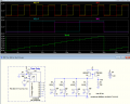
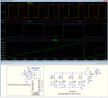
Below is the sim using a BJT as a poor-man's current-to-voltage converter to make the signal steps (roughly) equal and amplify the voltage:
Note that the transistor is operated inverted (emitter and collector reversed) which reduces the Beta of the transistor to about 4 so the gain of the circuit is not impractically high.
(It may look rather like an emitter follower circuit, but the emitter is actually acting as the collector, since it's reverse-biased and the collector-base junction is forward biased).
You likely will have to adjust the value of R2 to get the desired voltage span for the transistor you have.
1700093946796.png
 
Last edited:

Thread Starter

Sensacell

Joined Jun 19, 2012
3,789
Nice, the transistor junction pins the ladder voltage to a diode drop below V+ so the steps are more linear.
This would not be a viable production solution, the gain of this transistor would not be predictable enough, unit to unit?

An opamp in transimpedance mode would do the trick, maybe an 8 pin dual part, one amp per 4 bits.
 

Ian0

Joined Aug 7, 2020
13,310
Nice, the transistor junction pins the ladder voltage to a diode drop below V+ so the steps are more linear.
This would not be a viable production solution, the gain of this transistor would not be predictable enough, unit to unit?

An opamp in transimpedance mode would do the trick, maybe an 8 pin dual part, one amp per 4 bits.
How much will it drift with temperature?
 

k1ng 1337

Joined Sep 11, 2020
1,038
I need to think about this a bit, the tutorial assumes the logic inputs are solid logic levels, 0V or Vcc
This would not be the case with the DIP switch, the inputs would either be LOW, or HIGH Z. (floating) or the reverse, Vcc or floating.

My gut tells me this is problematic, some mental chewing is required.
8-3 Encoder IC and 8 pull resistors should assert the correct bits at startup since its combinational logic.
 

MrChips

Joined Oct 2, 2009
35,279
Yeah, that idea did not make any sense to me, you need to resolve 8 bits to identify an address ranging from 0 to 255.
Sorry, I must have been asleep at the wheel when I suggested an 8-line to 3-line encoder.

How about a simple UART transmitter?
It takes only one UART RX line at the receiver.
 

Thread Starter

Sensacell

Joined Jun 19, 2012
3,789
Sorry, I must have been asleep at the wheel when I suggested an 8-line to 3-line encoder.

How about a simple UART transmitter?
It takes only one UART RX line at the receiver.
Actually that gives me an idea!

If I program a tiny little MCU to do the job, with 8 IO lines, and a really crude serial output, it becomes a very simple 2 -part solution.
Use the internal pullups on the IO lines, then maybe 3 parts if you count the bypass capacitor.

Then the host system only needs 1 IO pin to read the serial input!
 

Ian0

Joined Aug 7, 2020
13,310
Actually that gives me an idea!

If I program a tiny little MCU to do the job, with 8 IO lines, and a really crude serial output, it becomes a very simple 2 -part solution.
Use the internal pullups on the IO lines, then maybe 3 parts if you count the bypass capacitor.

Then the host system only needs 1 IO pin to read the serial input!
Only a 2-part solution if you don’t need a programming connection on board for the tiny processor.
 

MrChips

Joined Oct 2, 2009
35,279
Actually that gives me an idea!

If I program a tiny little MCU to do the job, with 8 IO lines, and a really crude serial output, it becomes a very simple 2 -part solution.
Use the internal pullups on the IO lines, then maybe 3 parts if you count the bypass capacitor.

Then the host system only needs 1 IO pin to read the serial input!
If you can accept just two I/O pins then there are more solutions available using SPI.
 

crutschow

Joined Mar 14, 2008
38,913
his would not be a viable production solution, the gain of this transistor would not be predictable enough, unit to unit?
Not sure how much a transistor's inverting gain varies between units.
But my previous circuit without the transistor (post #20) would be accurate within the resistor and supply voltage tolerances.
An opamp in transimpedance mode would do the trick, maybe an 8 pin dual part, one amp per 4 bits.
How would that work with a single supply voltage, since a transimpedance amp inverts the signal?
 

crutschow

Joined Mar 14, 2008
38,913
Here's another, more stable alternate for an A/D input:
It uses a dual-transistor current-mirror to convert the matrix current to voltage, which is not significantly affected by the value of Beta or temperature, so should not show much variation from unit-to-unit.
Best would be to use dual matched transistors in one package, such as the PMP3906AYS-QZ (matched to 2mV Vbe and US$0.51 each in unit quantity).

1700163610455.png
 
Last edited:

Ian0

Joined Aug 7, 2020
13,310
Here's another, more stable alternate:
It uses a dual-transistor current mirror to convert the matrix current to voltage, which is not significantly affected by the value of Beta or temperature, so should not show much variation from unit-to-unit.
Best would be to use dual matched transistors in one case, such as the PMP3906AYS-QZ (matched to 2mV Vbe and US$0.51 each in unit quantity).
I have actually used that circuit (so long ago, I had forgotten about it). It is easily repeatable enough to be used commercially.
Compared to my 4051 and single pull up resistor:
more components, but cheaper components, and fewer pins
 

Thread Starter

Sensacell

Joined Jun 19, 2012
3,789
Here's another, more stable alternate for an A/D input:
It uses a dual-transistor current-mirror to convert the matrix current to voltage, which is not significantly affected by the value of Beta or temperature, so should not show much variation from unit-to-unit.
Best would be to use dual matched transistors in one package, such as the PMP3906AYS-QZ (matched to 2mV Vbe and US$0.51 each in unit quantity).

View attachment 307747
Yes! this is a really nice solution!!

My microcontroller idea was coming in at around $1.10 each.
Would you be so kind as to post the .asc file so I can play with it?
 

AnalogKid

Joined Aug 1, 2013
12,287
Last edited:

AnalogKid

Joined Aug 1, 2013
12,287
1 am postings ... You'd think I would learn, but where's the fun in that?

OK, based on Ian's snotty little reality check, try this.

For the dual 4-bit ladders, make the ladder impedance 100 K, and add a 1 K pull down resistor from each switch pin to GND. The switches pull up to Vcc.


24 little critters, true, but it brings the per-board cost up to a gigundous $0.24 in SMT, and $0.60 in PTH.

ak
 
Top