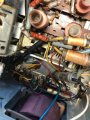
Telefunken Operette 6

MisterBill2

Joined Jan 23, 2018
18,585
YES! That is the purpose of the grounding pin. It will satisfy the intent of the capacitors very well. And it might possibly improve reception a bit on the short wave and long wave bands.
Of course, because the radio has a power transformer the hazard of a chassis intentionally connected to the mains is much less likely.
 
Last edited:

Thread Starter

8302

Joined Nov 24, 2022
17
MisterBill2, you said Yes, that is the purpose of the grounding pin. Was that in reply to “ do I need to ground to the chassis” or do I have an Aerial Earth?
 

MisterBill2

Joined Jan 23, 2018
18,585
MisterBill2, you said Yes, that is the purpose of the grounding pin. Was that in reply to “ do I need to ground to the chassis” or do I have an Aerial Earth?
Grounding the chassis is intended, by one set of reasoning, to "increase safety", given that an accidental connection of the mains circuit to the chassis create a shock hazard. Such an accidental connection is unlikely in this radio model.
From the circuit shown in your initial post, #1, it seems that an "Arial Earth" connection to the chassis is already present. A direct and deliberate "earth connection" is usually suggested for best reception, but for the majority of broadcast signals the benefit is hard to discern.
So adding the grounding function of a three-wire plug will primarily be a safety benefit, but it may also improve the short wave reception as well. You will need some sort of antenna with this receiver, as it does not appear to have a loop antenna internally.
 

Thread Starter

8302

Joined Nov 24, 2022
17
OK, I have the double cap installed and am now working on the rectifier. The first pic shows the bottom of the chassis where the rec is wired in. The second pic shows the rec with everything in the way removed. the third pic shows where the wires are connected to a connection bar ( sorry, I don’t know the correct terminology), the grey wire goes to connection point 2 where it hooks up with 5 different caps, the yellow wires go to different connection points and hook up to different green wires that go to the transformer. The red wire goes to another connection point and hooks up with a brown wire that goes to the top of the chassis to another connection bar. My question is this; I got the rectifier that was suggested to me but I am not sure how to attach it to the wiring. I am guessing that the 2 yellows are positive and are soldered to the plus side of the rec. The other 2 are a mystery to me! Any help will be much appreciated.
BC1A8E80-8916-4C5D-9044-29E333A3654C.jpegC7CF94CD-FC47-46DA-A807-CE7D44795B94.jpeg971C021D-3AB8-4518-ABAE-3E1E05CF2AB1.jpegC97CCCB6-4211-4AAA-84D2-1AC94584F2F7.jpeg3F6115F7-7FE4-4589-97E1-1720AF3B6763.jpeg3A8B2228-BB1B-4B6B-879E-454132562154.jpeg6F0DAD5D-662A-406E-A94E-C73A1ED1EF44.jpeg3A30FD4B-63D5-46A3-845D-D24931AB93EF.jpeg
 

Attachments

MisterBill2

Joined Jan 23, 2018
18,585
Looking at the circuit shown in posts #1 and #2, there are four connections on the rectifier, which I do not recall seeing the ratings of it. That rectifier should have four terminals, with one marked "+" and one marked "-". The other two terminals may be marked "AC", or they may not be marked at all.
I see in the photos that one wire has a + mark and another has the - mark so that part is clear.
What is seriously bothering me is that it does look like a bunch of parts have been removed.

I should have made it clear THAT IS NOT HOW TO REPAIR ELECTRONIC DEVICES. I certainly hope that the receiver will operate when they are returned to where they were.
The four wires that went to the rectifier need to be traced back to their origins, which are the circuit common, which may be the chassis, while two wires connect to the transformer, and the remaining wire connects to the positive terminal of the first capacitor section. My guess is that the two yellow wires connect to the transformer, but that needs to be verified first.
 

Dodgydave

Joined Jun 22, 2012
11,306
The Bridge Rectifier can be bolted to the chassis, and the wires extended or replaced to it. Easy to start from the transformer and follow it to the rectifier to find the AC wires, then the DC is marked up +/-.
 

LesJones

Joined Jan 8, 2017
4,191
Another point that might be worth considering is that the forward resistance of a silicon rectifier will be much less then that of a selenium rectifier. It might be worth adding a resistor in series with the positive output of the silicon rectifier. I doubt that 8302 has any means of measuring the forward resistance of the old selenium rectifier (The resistance range on a DMM would not give a sensible reading.) so I could only make a wild guess at a suitable value. All the valve equipment I worked on over 60 years ago use valve rectifiers.

Les.
 

MisterBill2

Joined Jan 23, 2018
18,585
The best choice would have been to put the bridge above the chassis , removing the cover from the selenium rectifier assembly and having the maximum length of the original wires, not disturbing the coils and wires below.
While I can believe the 1000 PIV rating on the data sheet that I saw, the 30 amp part does not agree with the wire sizes that I see for the connections. But for the current drawn by the receiver circuit it does not seem like a heat sink will be needed.
 
Thread starter Similar threads Forum Replies Date
R Analog & Mixed-Signal Design 32
Top