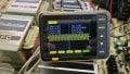
Technics SU VX-800 with blown components (another one)

MrChips

Joined Oct 2, 2009
35,198
Continue testing with 1 kHz sine wave input and with loudspeaker connected. Put a 470 μF - 1000 μF capacitor in series with the loudspeaker to protect the loudspeaker. Keep the VOLUME control low to show moderate distortion.

Show the oscilloscope signals at the base and emitter of Q504 and Q506.
Test at resistors R510, R512, R514 if these are safer to reach.

Were Q504 and Q506 ever replaced?

Q504 2SC3944
Q506 2SA1535

With the power off,
check resistors R516, R518, R566, R568 in-circuit (all 2.2 Ω)
check resistors R548, R550, R570, R572 in-circuit (all 0.22 Ω)
 

Thread Starter

alprampo

Joined May 29, 2026
43
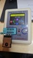
No, Q504 and Q506 were not replaced. I removed them from the PCB and tested them with a component tester, and they passed. the tester is below,
1790886226066.jpeg
However, since the test current on these multi-function component testers is extremely low, could be sometimes give a false positive under actual circuit conditions, so I will try to replace if I have spares that can be fit.
Update will come.
Thanks
 

Thread Starter

alprampo

Joined May 29, 2026
43
Continue testing with 1 kHz sine wave input and with loudspeaker connected. Put a 470 μF - 1000 μF capacitor in series with the loudspeaker to protect the loudspeaker. Keep the VOLUME control low to show moderate distortion.

Show the oscilloscope signals at the base and emitter of Q504 and Q506.
Test at resistors R510, R512, R514 if these are safer to reach.

Were Q504 and Q506 ever replaced?

Q504 2SC3944
Q506 2SA1535

With the power off,
check resistors R516, R518, R566, R568 in-circuit (all 2.2 Ω)
check resistors R548, R550, R570, R572 in-circuit (all 0.22 Ω)

You hit the nail on the head!

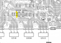
The resistors themselves were fine, but after inspecting the PCB under a magnifying glass, I found both R514 cracked pads/traces in that section. I repaired the traces and reinstalled the board.
1791131598512.png
I powered the unit through the Dim Bulb first, and everything looked stable. I then switched to direct mains power and injected the 1 kHz sine wave into the input.

When checking the speaker output on the oscilloscope, I noticed a strong high-frequency oscillation superimposed on the signal, making it impossible to read the 1 kHz sine wave cleanly.
1791131703002.jpeg
Could this high-frequency oscillation be caused by the replacement transistors for Q428 and Q430? The ones currently installed have a lower Transition Frequency ($f_T = 100\text{ MHz}$) compared to the original parts ($f_T = 200\text{ MHz}$).

Update on Audio Test:

I tried connecting a speaker and playing music/audio. To my surprise, the sound coming from the speaker is completely clean to the ear! I monitored the temperatures for a while: nothing is overheating (drivers and power transistors remain cool), and there is no sign of thermal instability or smoke.

However, the thick high-frequency trace is still present on the oscilloscope.

Thanks!
 

MrChips

Joined Oct 2, 2009
35,198
Try to use your oscilloscope to find where the oscillation originates.
Is it before Q502 or after Q502?
C506, 0.1 μF would have suppressed oscillation.
 

Thread Starter

alprampo

Joined May 29, 2026
43
Try to use your oscilloscope to find where the oscillation originates.
Is it before Q502 or after Q502?
C506, 0.1 μF would have suppressed oscillation.
I checked Q502 with the scope, and the high-frequency oscillation is present on both the base and the emitter.

A key detail: the oscillation only triggers when the speaker switch is engaged (connecting the load). Once triggered, switching the speaker back OFF does not stop the oscillation—it remains active, though its peak-to-peak amplitude decreases slightly.

Looking at Q428 and Q430:

  • Oscillation is present on both transistors, but the amplitude is significantly higher on their emitters.
On IC402:

  • Pin 5 remains completely clean.
  • Pin 6 and Pin 7 both show high-frequency oscillation.
All these tests were performed with no input signal and the volume set to minimum (0).

Thanks!
 

MrChips

Joined Oct 2, 2009
35,198
There is negative feedback from the power stage output to IC402 pin-6.

You need to check C508, C518 (0.068 μF) and R520 (I cannot read the value, 10 Ω 1/2W ?)

Try temporarily, 0.01-0.1 μF from R570-R572 node to GND.
 
Top