Tank circuit amplifier help

Thread Starter

Msaf1123

Joined Mar 25, 2016
5
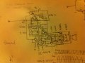
I've been looking online for awhile now and all the tank circuit amplifiers i see are either too complicated for my beginner mind to understand or just uses an op amp (which I would prefer to avoid). I would like to know if all the complicated circuitry is necessary? Or can I just use this circuit to amplify? I know it will only give me a square wave if it works, but I can do with that. By the way, all transistors are standard npn bjts
 

Attachments

#12

Joined Nov 30, 2010
18,224
That is so hard to read! It looks like a tuned AM antenna straight to a speaker. What's up?
What voltage? What frequency? What is the load impedance? Why aren't there any resistors?
 

Thread Starter

Msaf1123

Joined Mar 25, 2016
5
That is so hard to read! It looks like a tuned AM antenna straight to a speaker. What's up?
What voltage? What frequency? What is the load impedance? Why aren't there any resistors?
It's suppose to to be an fm receiver, i didn't think that the transistors needed resistors since the signal voltage would be so low, and the input voltage is 9v but i didn't think that mattered if I'm just trying to find out if this general configuration would work. I don't excactly understand impedance at the moment. Should I draw it bigger?
 

#12

Joined Nov 30, 2010
18,224
I don't think you're anywhere close. If you start with 100 MHz carrier frequency, modulated in its frequency, you have to get it down to audio frequency and change the frequency variations into amplitude variations. I don't see how this would work.
Smarter people than me will be here in a few hours.
 

seanstevens

Joined Sep 22, 2009
253
This might work as a super regenerative receiver configuration. Receiving an FM frequency and generating the same with a few KHz difference and demodulate it.
 

Thread Starter

Msaf1123

Joined Mar 25, 2016
5
This might work as a super regenerative receiver configuration. Receiving an FM frequency and generating the same with a few KHz difference and demodulate it.
How about this one. I used the previous circuit to amplify the signal, then used another npn to turn ac into pulsing dc. I then used L2 to smooth out the pulsing signals into alternating voltage (I think that's how inductors work; the whole flywheel analogy). I also added two npns and two pnps on either side ( one in inverse order) so that when the frequencies either get too high or too low, they will drive the voltage back to zero or up from zero to make sure there's enough difference in voltage. I then used a set of pnp and npn
 

Thread Starter

Msaf1123

Joined Mar 25, 2016
5
To turn it back into ac and amplified it one more time before hooking it up to the speaker. Also, could you help me understand pll?
 

Attachments

Top