Facebook
 Google
 GitHub
 Linkedin
Hello All,
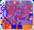
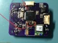
I designed a custom PCB that was supposed to run an STM32F411RET6 off an external 8Mhz cystal oscillator.
This is the first custom PCB I have done for an STM32 chip, so I am never quite sure when I am having hardware versus software errors. I have attached some pictures of my PCB below. You'll notice a few "bodges":
· One of the VCC and VDD pins were swapped in the schematic, so I cut the traces and jumped the decoupling caps. I had to replace the main MCU entirely because of this mistake.
· The BOOT0 pin was left floating, so I have a jumper wire connecting it to GND.
· The VCAP1 pin was left floating, so I have a jumper wire connecting it to VCC (still no capacitor in place).
In order to eliminate some of the guesswork, I am simply trying to configure the HSI and PLL as my application is not really THAT timing critical, plus I have all the other hardware to proof out still.
For what its worth, here are the components I selected for the HSE:
Xtal <--------------- link
Caps <--------------- link
I can connect to the chip with my StLink-V2 via SWD, and can erase & program it with the St-Link Utility.
I am programming and debugging the chip with a trial license of IAR-EWARM.
I have used one of the pre-written STM32F411 Nucleo cube projects to get an ERM motor "blinking." The code is shown below:
However, the program often crashes when I call HAL_RCC_ClockConfig() function in my main.cpp file.
If I comment out the SystemClock_Config() the program runs, but the SystemCoreClock defaults to 16Mhz.
It usually seems to fail within the stm32f4xx_hall_rcc.c file when either two of the following functions are called:
Usually if I pause the CPU after hanging here it appears the CPU is in the HardFault_Handler().
Occasionally the program will manually step its way through the entire configuration, but attaching a watch on the SystemCoreClock still shows it at 16Mhz.
Any ideas as to what I should do?
I designed a custom PCB that was supposed to run an STM32F411RET6 off an external 8Mhz cystal oscillator.
This is the first custom PCB I have done for an STM32 chip, so I am never quite sure when I am having hardware versus software errors. I have attached some pictures of my PCB below. You'll notice a few "bodges":
· One of the VCC and VDD pins were swapped in the schematic, so I cut the traces and jumped the decoupling caps. I had to replace the main MCU entirely because of this mistake.
· The BOOT0 pin was left floating, so I have a jumper wire connecting it to GND.
· The VCAP1 pin was left floating, so I have a jumper wire connecting it to VCC (still no capacitor in place).
In order to eliminate some of the guesswork, I am simply trying to configure the HSI and PLL as my application is not really THAT timing critical, plus I have all the other hardware to proof out still.
For what its worth, here are the components I selected for the HSE:
Xtal <--------------- link
Caps <--------------- link
I can connect to the chip with my StLink-V2 via SWD, and can erase & program it with the St-Link Utility.
I am programming and debugging the chip with a trial license of IAR-EWARM.
I have used one of the pre-written STM32F411 Nucleo cube projects to get an ERM motor "blinking." The code is shown below:
Code:
/* Includes ------------------------------------------------------------------*/
#include "main.h"

/** @addtogroup STM32F4xx_HAL_Examples
* @{
*/

/** @addtogroup GPIO_IOToggle
* @{
*/

/* Private typedef -----------------------------------------------------------*/
/* Private define ------------------------------------------------------------*/
/* Private macro -------------------------------------------------------------*/
/* Private variables ---------------------------------------------------------*/
static GPIO_InitTypeDef GPIO_InitStruct;

/* Private function prototypes -----------------------------------------------*/
static void SystemClock_Config(void);
static void Error_Handler(void);

/* Private functions ---------------------------------------------------------*/

/**
* @brief Main program
* @param None
* @retval None
*/
int main(void)
{
/* STM32F4xx HAL library initialization:
- Configure the Flash prefetch, instruction and Data caches
- Configure the Systick to generate an interrupt each 1 msec
- Set NVIC Group Priority to 4
- Global MSP (MCU Support Package) initialization
*/
HAL_Init();

/* Configure the system clock to 100 MHz */
SystemClock_Config();

/*##-1- Enable GPIOA Clock (to be able to program the configuration registers) */
__HAL_RCC_GPIOC_CLK_ENABLE();

/*##-2- Configure PA05 IO in output push-pull mode to drive external LED ###*/
GPIO_InitStruct.Pin = GPIO_PIN_8;
GPIO_InitStruct.Mode = GPIO_MODE_OUTPUT_PP;
GPIO_InitStruct.Pull = GPIO_PULLUP;
GPIO_InitStruct.Speed = GPIO_SPEED_FAST;
HAL_GPIO_Init(GPIOC, &GPIO_InitStruct);

/*##-3- Toggle PA05 IO in an infinite loop #################################*/
while (1)
{
HAL_GPIO_TogglePin(GPIOC, GPIO_PIN_8);

/* Insert a 100ms delay */
HAL_Delay(100);
}
}

/**
* @brief System Clock Configuration
* The system Clock is configured as follow :
* System Clock source = PLL (HSI)
* SYSCLK(Hz) = 100000000
* HCLK(Hz) = 100000000
* AHB Prescaler = 1
* APB1 Prescaler = 2
* APB2 Prescaler = 1
* HSI Frequency(Hz) = 16000000
* PLL_M = 16
* PLL_N = 400
* PLL_P = 4
* PLL_Q = 7
* VDD(V) = 3.3
* Main regulator output voltage = Scale2 mode
* Flash Latency(WS) = 3
* @param None
* @retval None
*/
static void SystemClock_Config(void)
{
RCC_ClkInitTypeDef RCC_ClkInitStruct;
RCC_OscInitTypeDef RCC_OscInitStruct;

/* Enable Power Control clock */
__HAL_RCC_PWR_CLK_ENABLE();

/* The voltage scaling allows optimizing the power consumption when the device is
clocked below the maximum system frequency, to update the voltage scaling value
regarding system frequency refer to product datasheet. */
__HAL_PWR_VOLTAGESCALING_CONFIG(PWR_REGULATOR_VOLTAGE_SCALE2);

/* Enable HSI Oscillator and activate PLL with HSI as source */
RCC_OscInitStruct.OscillatorType = RCC_OSCILLATORTYPE_HSI;
RCC_OscInitStruct.HSIState = RCC_HSI_ON;
RCC_OscInitStruct.HSICalibrationValue = 0x10;
RCC_OscInitStruct.PLL.PLLState = RCC_PLL_ON;
RCC_OscInitStruct.PLL.PLLSource = RCC_PLLSOURCE_HSI;
RCC_OscInitStruct.PLL.PLLM = 16;
RCC_OscInitStruct.PLL.PLLN = 400;
RCC_OscInitStruct.PLL.PLLP = RCC_PLLP_DIV4;
RCC_OscInitStruct.PLL.PLLQ = 7;
if(HAL_RCC_OscConfig(&RCC_OscInitStruct) != HAL_OK)
{
Error_Handler();
}

/* Select PLL as system clock source and configure the HCLK, PCLK1 and PCLK2
clocks dividers */
RCC_ClkInitStruct.ClockType = (RCC_CLOCKTYPE_SYSCLK | RCC_CLOCKTYPE_HCLK | RCC_CLOCKTYPE_PCLK1 | RCC_CLOCKTYPE_PCLK2);
RCC_ClkInitStruct.SYSCLKSource = RCC_SYSCLKSOURCE_PLLCLK;
RCC_ClkInitStruct.AHBCLKDivider = RCC_SYSCLK_DIV1;
RCC_ClkInitStruct.APB1CLKDivider = RCC_HCLK_DIV2;
RCC_ClkInitStruct.APB2CLKDivider = RCC_HCLK_DIV1;
if(HAL_RCC_ClockConfig(&RCC_ClkInitStruct, FLASH_LATENCY_3) != HAL_OK)
{
Error_Handler();
}
}

/**
* @brief This function is executed in case of error occurrence.
* @param None
* @retval None
*/
static void Error_Handler(void)
{
while(1)
{
}
}

#ifdef USE_FULL_ASSERT
/**
* @brief Reports the name of the source file and the source line number
* where the assert_param error has occurred.
* @param file: pointer to the source file name
* @param line: assert_param error line source number
* @retval None
*/
void assert_failed(uint8_t* file, uint32_t line)
{
/* User can add his own implementation to report the file name and line number,
ex: printf("Wrong parameters value: file %s on line %d\r\n", file, line) */

/* Infinite loop */
while (1)
{
}
}
#endif

/**
* @}
*/

/**
* @}
*/If I comment out the SystemClock_Config() the program runs, but the SystemCoreClock defaults to 16Mhz.
It usually seems to fail within the stm32f4xx_hall_rcc.c file when either two of the following functions are called:
Code:
/* Update the SystemCoreClock global variable */
SystemCoreClock = HAL_RCC_GetSysClockFreq() >> AHBPrescTable[(RCC->CFGR & RCC_CFGR_HPRE)>> POSITION_VAL(RCC_CFGR_HPRE)];

/* Configure the source of time base considering new system clocks settings*/
HAL_InitTick (TICK_INT_PRIORITY);Occasionally the program will manually step its way through the entire configuration, but attaching a watch on the SystemCoreClock still shows it at 16Mhz.
Any ideas as to what I should do?
Attachments
-
 183.2 KB Views: 7
 -
 183.2 KB Views: 7