Facebook
 Google
 GitHub
 Linkedin

I am working on a discrete component project design, that requires a manual potentiometer, to be replaced with active components, so as to have electronic controle to it, as well as manual controle
.
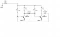
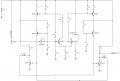
The potentiometer, in the original circuit is used to bias a square wave multivibrator, so as for it to be able to work in PWM, without to much frequency change.
The pot is set up that each end of the pot is connected to the base of each transistor, as the pot is turned, the ratio of current to each transistor remains the same, to keep the frequency stable, but allows the width of the pulses to change accordingly.
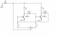
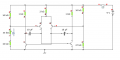
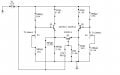
So here is my first design using active devices, to synthesize as close as possible a potentiometer.
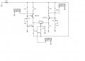
This is a first prototype, 'proof of concept' to see if it will work, it does work, but needs lots of rework to make it less sensitive to input voltasge change, to give a wider range of input voltage.
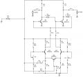
It is designed where the right side transistor output, biased heavily bringing the voltage at its collector to around 5v. While the left side ttransistor is biaased close to cutoff, to have its collector at 11v.
Then the middle ttansistor is introduced to be biased so as to pull both the right, and left side transistors outputs close to a quiescence of 8v.
The trimmers are used to balance the bridge, at the 8v level.
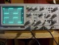
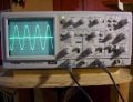
With this setup the input signal goes to the middle transistoer base, which will unbakance this bridge one direction or the other, depending on the input signal; amplitude.
The middle transistor acts as the center tap of a potentiometer, while the differential transistor pair acts as the both ends of a potentiometer, when the outputs are quiescent at 8v. then this synthesizes a potentiometer whose setting is in the middle, as the signal drives the middle transistor on harder, it synthesizes, a potentiometer, whose setting is such that the right side is becoming more positive while the left side is less positive, at the same ratio.
Same concept as a differential amp, only with this the input signal is introduced to both transistor enmitters, so there is no inverting and noninveerting inputs, but one input to a center tap, that changes the output with varying signal amplitude. Just as a pot, has a center tap.
.
The potentiometer, in the original circuit is used to bias a square wave multivibrator, so as for it to be able to work in PWM, without to much frequency change.
The pot is set up that each end of the pot is connected to the base of each transistor, as the pot is turned, the ratio of current to each transistor remains the same, to keep the frequency stable, but allows the width of the pulses to change accordingly.
So here is my first design using active devices, to synthesize as close as possible a potentiometer.
This is a first prototype, 'proof of concept' to see if it will work, it does work, but needs lots of rework to make it less sensitive to input voltasge change, to give a wider range of input voltage.
It is designed where the right side transistor output, biased heavily bringing the voltage at its collector to around 5v. While the left side ttransistor is biaased close to cutoff, to have its collector at 11v.
Then the middle ttansistor is introduced to be biased so as to pull both the right, and left side transistors outputs close to a quiescence of 8v.
The trimmers are used to balance the bridge, at the 8v level.
With this setup the input signal goes to the middle transistoer base, which will unbakance this bridge one direction or the other, depending on the input signal; amplitude.
The middle transistor acts as the center tap of a potentiometer, while the differential transistor pair acts as the both ends of a potentiometer, when the outputs are quiescent at 8v. then this synthesizes a potentiometer whose setting is in the middle, as the signal drives the middle transistor on harder, it synthesizes, a potentiometer, whose setting is such that the right side is becoming more positive while the left side is less positive, at the same ratio.
Same concept as a differential amp, only with this the input signal is introduced to both transistor enmitters, so there is no inverting and noninveerting inputs, but one input to a center tap, that changes the output with varying signal amplitude. Just as a pot, has a center tap.
Last edited: