Synchronous Rectifier IC (SKR1000) parameter clarification

Thread Starter

jlawley1969

Joined Feb 22, 2021
97
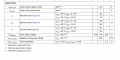
Hi so as you can see in the attached image, there are the parameters "output source peak current" and the one below it. These are in the electrical characteristics and not in the absolute max characteristics section. I am unsure what is meant by this as it could be several things in my mind. (I can list all the things I thought it could mean but that would just probably waste time )
https://www.mouser.com/datasheet/2/389/dm00551455-1799344.pdf
 

Attachments

ronsimpson

Joined Oct 7, 2019
3,037
Here is a typical circuit from the data sheet. The "diode" is the MOSFET and not the IC. The IC decides when the MOSFET is on or off. There is a pin on the IC "GO" that drives the Gate of the MOSFET. The currents you are talking about are the current that the IC can push into the MOSFET. The Gate has a large capacitor inside.
1635979469303.png
 

Thread Starter

jlawley1969

Joined Feb 22, 2021
97
Here is a typical circuit from the data sheet. The "diode" is the MOSFET and not the IC. The IC decides when the MOSFET is on or off. There is a pin on the IC "GO" that drives the Gate of the MOSFET. The currents you are talking about are the current that the IC can push into the MOSFET. The Gate has a large capacitor inside.
View attachment 251822
Ok cool that is what I thought was most logical
Another question(if you have the insight)
so the current sunk into the gate is proportional to the gates capacitance? Does the voltage across the drain / source effect it? I have some assumptions but would be more clear cut if someone explained explicitly
 

ronsimpson

Joined Oct 7, 2019
3,037
so the current sunk into the gate is proportional to the gates capacitance? Does the voltage across the drain / source effect it?
Yes,
At DC the Gate current is almost Zero. If you hold the Gate a 0V or 10V there is no current.
Changing the voltage takes current!
1) The Gate to Source capacitance is just like any capacitor. It takes current to charge up/discharge the cap. (charge 0 to 10 and 10 back to 0)
2) The Gate to Drain cap is different. Assume the Gare voltage is 0 or 10V. Assume the Drain is switching a 0 to100V supply.
While the Gate is driven from 0 to 10V the MOSFET turns on and the Drain voltage goes from 100V to 0V. So the G-S cap starts out with 0V on one end and 100V on the other end; then after the MOSFET is on it has 10V-0V across it. So there is 110V difference in charge. (the turn off side does the same thing in reverse) In this case you are charging to 11x the voltage.

In the case of G-D capacitance the voltage being switched does effect how much current it takes to charge the capacitance.
In the case of G-S capacitance only the Gare voltage effects the amount of current it takes.
 
Top