Facebook
 Google
 GitHub
 Linkedin
Hi all,
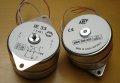
I'm very new to electronics, and I'm looking to understand this motor assembly which I have removed from a record player.
The motor I believe to be a synchronous motor (Sev Litovel M303 16V 2VA 300rpm).
I have a few questions on this circuit:
- My very limited understanding of synchronous motors is that they require 3 phase power supply to the stator, and I understand in principle how these types of motors work. However, clearly this is a small motor supplied by AC power not 3 phase. How is a rotating electromagnetic field set up using only AC current?
- What is the function of the two capacitors?
- What is the arrangement of the wires likely to be inside the motor?
- Is there some kind of controller built into the motor?
I have tried drawing a circuit diagram, but without an understanding of how the wires are arranged inside the motor I am really struggling to understand how the whole system works.
If anyone could be kind enough to offer any explanations, or point me in the direction of anything that could help me answer the above questions I would really appreciate it!
Many thanks,
M