Facebook
 Google
 GitHub
 Linkedin
Hello,
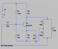
Here is an oscillator I designed, please take a look at it and tell me what you think.
Thanks
Here is an oscillator I designed, please take a look at it and tell me what you think.
Thanks
Attachments
-
 19.3 KB Views: 27
 -
1.9 KB Views: 6