SunFounder I2C LCD1602 for PIC24FJ128GA110

Thread Starter

jcrunchwrap

Joined Jul 24, 2023
19
If I were in your position I would reverse engineer the Sunfounder I2C LCD1602 board, document it, and put the information in a blog. This could be very useful to someone else.

Start with the 16-pin LCD pinout.
View attachment 299071

Get the HD44780 documentation and learn how to initialize and drive the LCD in 4-bit mode.
https://www.sparkfun.com/datasheets/LCD/HD44780.pdf

Get the PCF8574 documentation and study how it interfaces I2C to 8-bit parallel port.
https://www.ti.com/lit/ds/symlink/pcf8574.pdf

View attachment 299072
Get a DMM, trace and document the connections between the PCF8574 and the LCD module.

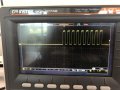
Get the oscilloscope out and start writing and testing code to send parallel data to the LCD module.
Document your findings.

If I find the time I would even order a Sunfounder I2C LCD1602 for myself and do this for you as this looks like a very useful exercise.
Thanks for your reply !
I also have found a very interesting tutorial : https://deepbluembedded.com/interfacing-i2c-lcd-16x2-tutorial-with-pic-microcontrollers-mplab-xc8/ in case someone needs that.
I will complete my code to try and see if i manage to display something, and if it works, i will put my code/documents in the blog.
Thank you again so much for your help and I will let you know if i managed to display something, hopefully today !
 

MrChips

Joined Oct 2, 2009
34,900
Thanks for your reply !
I also have found a very interesting tutorial : https://deepbluembedded.com/interfacing-i2c-lcd-16x2-tutorial-with-pic-microcontrollers-mplab-xc8/ in case someone needs that.
I will complete my code to try and see if i manage to display something, and if it works, i will put my code/documents in the blog.
Thank you again so much for your help and I will let you know if i managed to display something, hopefully today !
That is a very informative link.

You need to check the I2C address selection and the 8-bit port assignments.
There is no guarantee that the software driver matches the port assignments. Only a check on the PCB connections will tell you how they are connected. This is what we are looking at from the various sources:

PCF8574 = LCD1602
pin-4 P0 = pin-4 RS
pin-5 P1 = pin-5 RW
pin-6 P2 = pin-6 E
pin-7 P3 = (LED backlight enable?)
pin-8 GND = pin-1 GND
pin-9 P4 = pin-11 D4
pin-10 P5 = pin-12 D5
pin-11 P6 = pin-13 D6
pin-12 P7 = pin-14 D7

pin-16 Vcc = pin-2 Vcc
 

Thread Starter

jcrunchwrap

Joined Jul 24, 2023
19
That is a very informative link.

You need to check the I2C address selection and the 8-bit port assignments.
There is no guarantee that the software driver matches the port assignments. Only a check on the PCB connections will tell you how they are connected. This is what we are looking at from the various sources:

PCF8574 = LCD1602
pin-4 P0 = pin-4 RS
pin-5 P1 = pin-5 RW
pin-6 P2 = pin-6 E
pin-7 P3 = (LED backlight enable?)
pin-8 GND = pin-1 GND
pin-9 P4 = pin-11 D4
pin-10 P5 = pin-12 D5
pin-11 P6 = pin-13 D6
pin-12 P7 = pin-14 D7

pin-16 Vcc = pin-2 Vcc
So for the I2C address, A2 A1 A0 are pulled up, so 1 1 1 which is gonna give the address 0x27 from what I have read on some articles/datasheet.
To check the pin, I did continuity testing. it worked!
 
Last edited:

Thread Starter

jcrunchwrap

Joined Jul 24, 2023
19
That is a very informative link.

You need to check the I2C address selection and the 8-bit port assignments.
There is no guarantee that the software driver matches the port assignments. Only a check on the PCB connections will tell you how they are connected. This is what we are looking at from the various sources:

PCF8574 = LCD1602
pin-4 P0 = pin-4 RS
pin-5 P1 = pin-5 RW
pin-6 P2 = pin-6 E
pin-7 P3 = (LED backlight enable?)
pin-8 GND = pin-1 GND
pin-9 P4 = pin-11 D4
pin-10 P5 = pin-12 D5
pin-11 P6 = pin-13 D6
pin-12 P7 = pin-14 D7

pin-16 Vcc = pin-2 Vcc
Now that i have checked all the pins, Im going to look for the initialization sequence od the lcd. I know that I have my scl and sda signals when i just initialize my i2c bus on the LCD pins because i see them on the scope. maybe i'm missing something during the initialization sequence of the lcd
 

Thread Starter

jcrunchwrap

Joined Jul 24, 2023
19
My SunFounder LCD1602 has arrived.
I will have answers for you in a few days.
oh thank you a lot! today i worked on improving my library. I can post it here if you want. I found some stuff that was missing, and now my lcd is blinking when the data is being sent. Still haven’t found out why there is no character displayed but I’ve made some progress in understanding the way it works !
 

MrChips

Joined Oct 2, 2009
34,900
I have created a blog here.

This is the code I used with a TI MSP430G2553 MCU.
This program initializes the I2C and LCD modules, clears the screen and sends out 'A' to the display once each second.
I have found that I have to power down the module and up again before running the MCU code.

The I2C interface will be different for the Microchip PIC.
You need to replace the I2C_Init( ) and I2C_Send( ) functions with PIC specific code.

The LCD functions are generic. There are only three functions demonstrated here.

LCD_init( )
LCD_cmd(char ch)
LCD_ch(char ch)

Note the 1ms delay before leaving the LCD_cmd( ) function.

C:
// SunFounder I2C LCD 1602
// MSP430G2553 I2C interface
// MrChips - 2023.07.29

//-------------------------------------
// includes
//-------------------------------------

#include "io430.h"

//-------------------------------------
// defines
//-------------------------------------

#define LED1 P1OUT_bit.P0
#define LED2 P1OUT_bit.P6

#define ON  1
#define OFF 0

#define SLAVE_ADDRESS 0x27
#define LCD_RS BIT0
#define LCD_RW BIT1
#define LCD_E  BIT2
#define LCD_BACKLITE BIT3

#define DELAY_10us       9
#define DELAY_100us    110
#define DELAY_200us    220
#define DELAY_500us    550
#define DELAY_1ms     1125
#define DELAY_1s   1125000

char IRQ_count;

//-------------------------------------
// functions
//-------------------------------------

void delay(unsigned long int d)
{
  while(--d);
}

//-------------------------------------
// I2C functions
//-------------------------------------

void I2C_Init(void)
{
  while (UCB0CTL1 & UCTXSTP);
  UCB0CTL1 |= UCSWRST;
  UCB0CTL0 = UCMST + UCMODE_3 + UCSYNC;
  UCB0CTL1 = UCSSEL_2 + UCSWRST;
  UCB0BR0 = 64;
  UCB0BR1 = 0;
  UCB0I2CSA = SLAVE_ADDRESS;
  UCB0CTL1 &= ~UCSWRST;        // clear software reset
  IE2 |= UCB0TXIE;             // enable interrupt
}

void I2C_Send(unsigned int d)
{
  IRQ_count = 0;
  UCB0TXBUF = d;
  while (UCB0CTL1 & UCTXSTP);
  UCB0CTL1 |= UCTR + UCTXSTT;   // start I2C
  delay(DELAY_200us);
}

#pragma vector = USCIAB0TX_VECTOR
__interrupt void USCIAB0TX_ISR(void)
{
  // first IRQ is received when START on SDA is sent
  ++IRQ_count;
  if (IRQ_count > 1)
  {
    UCB0CTL1 |= UCTXSTP;    // send STOP
  }
  IFG2 &= ~UCB0TXIFG;  // clear flag
}

//-------------------------------------
// LCD functions
//-------------------------------------

void LCD_cmd(char ch)
{
  char d;
  d = (ch & 0xF0) + LCD_BACKLITE; // send upper nybble
  I2C_Send(d);
  I2C_Send(d + LCD_E);            // pulse E high-low
  I2C_Send(d);
  I2C_Send(LCD_BACKLITE);

  d = ((ch << 4) & 0xF0) + LCD_BACKLITE;  // send lower nybble
  I2C_Send(d);
  I2C_Send(d + LCD_E);    // pulse E high-low
  I2C_Send(d);
  I2C_Send(LCD_BACKLITE);
  delay(DELAY_1ms);
}

void LCD_ch(char ch)
{
  char d;
  d = (ch & 0xF0) + LCD_RS + LCD_BACKLITE; // send upper nybble
  I2C_Send(d);
  I2C_Send(d + LCD_E);                     // pulse E high-low
  I2C_Send(d);
  I2C_Send(LCD_RS + LCD_BACKLITE);

  d = ((ch << 4) & 0xF0) + LCD_RS + LCD_BACKLITE;  // send lower nybble
  I2C_Send(d);
  I2C_Send(d + LCD_E);              // pulse E high-low
  I2C_Send(d);
  I2C_Send(LCD_RS + LCD_BACKLITE);
}

void LCD_init(void)
{
  LCD_cmd(0x02);  // home
  LCD_cmd(0x28);  // dual line, 4 bits
  LCD_cmd(0x06);  // increment mode
  LCD_cmd(0x0C);  // cursor turned off
  LCD_cmd(0x10);  // cursor right
  LCD_cmd(0x01);  // clear display
}

//-------------------------------------
// Initialization
//-------------------------------------

void Init_HW(void)
{
  P1DIR  = 0x01;
  P2DIR  = 0x00;
  P1OUT  = 0x00;
  P2OUT  = 0x00;

  // assign P1.6 and P1.7 to I2C
  P1SEL  = BIT6 + BIT7;
  P1SEL2 = BIT6 + BIT7;

  I2C_Init();
}

void Init(void)
{
  // Stop watchdog timer to prevent time out reset
  WDTCTL = WDTPW + WDTHOLD;

  // set DCO - Digitally-Controlled Oscillator frequency
  // change from 1MHz to 8MHz calibrated
  BCSCTL1 = CALBC1_8MHZ;
  DCOCTL  = CALDCO_8MHZ;

  Init_HW();
  __enable_interrupt();
}

//-------------------------------------
// main
//-------------------------------------

void main(void)
{
  Init();
  LCD_init();

  while(1)
  {
    LCD_ch('A');
    delay(DELAY_1s);
  }

}

//-------------------------------------
// end of main
//-------------------------------------
 
Last edited:

Thread Starter

jcrunchwrap

Joined Jul 24, 2023
19
I have created a blog here.

This is the code I used with a TI MSP430G2553 MCU.
This program initializes the I2C and LCD modules, clears the screen and sends out 'A' to the display once each second.
I have found that I have to power down the module and up again before running the MCU code.

The I2C interface will be different for the Microchip PIC.
You need to replace the I2C_Init( ) and I2C_Send( ) functions with PIC specific code.

The LCD functions are generic. There are only three functions demonstrated here.

LCD_init( )
LCD_cmd(char ch)
LCD_ch(char ch)

Note the 1ms delay before leaving the LCD_cmd( ) function.

C:
// SunFounder I2C LCD 1602
// MSP430G2553 I2C interface
// MrChips - 2023.07.29

//-------------------------------------
// includes
//-------------------------------------

#include "io430.h"

//-------------------------------------
// defines
//-------------------------------------

#define LED1 P1OUT_bit.P0
#define LED2 P1OUT_bit.P6

#define ON  1
#define OFF 0

#define SLAVE_ADDRESS 0x27
#define LCD_RS BIT0
#define LCD_RW BIT1
#define LCD_E  BIT2
#define LCD_BACKLITE BIT3

#define DELAY_10us       9
#define DELAY_100us    110
#define DELAY_200us    220
#define DELAY_500us    550
#define DELAY_1ms     1125
#define DELAY_1s   1125000

char IRQ_count;

//-------------------------------------
// functions
//-------------------------------------

void delay(unsigned long int d)
{
  while(--d);
}

//-------------------------------------
// I2C functions
//-------------------------------------

void I2C_Init(void)
{
  while (UCB0CTL1 & UCTXSTP);
  UCB0CTL1 |= UCSWRST;
  UCB0CTL0 = UCMST + UCMODE_3 + UCSYNC;
  UCB0CTL1 = UCSSEL_2 + UCSWRST;
  UCB0BR0 = 64;
  UCB0BR1 = 0;
  UCB0I2CSA = SLAVE_ADDRESS;
  UCB0CTL1 &= ~UCSWRST;        // clear software reset
  IE2 |= UCB0TXIE;             // enable interrupt
}

void I2C_Send(unsigned int d)
{
  IRQ_count = 0;
  UCB0TXBUF = d;
  while (UCB0CTL1 & UCTXSTP);
  UCB0CTL1 |= UCTR + UCTXSTT;   // start I2C
  delay(DELAY_200us);
}

#pragma vector = USCIAB0TX_VECTOR
__interrupt void USCIAB0TX_ISR(void)
{
  // first IRQ is received when START on SDA is sent
  ++IRQ_count;
  if (IRQ_count > 1)
  {
    UCB0CTL1 |= UCTXSTP;    // send STOP
  }
  IFG2 &= ~UCB0TXIFG;  // clear flag
}

//-------------------------------------
// LCD functions
//-------------------------------------

void LCD_cmd(char ch)
{
  char d;
  d = (ch & 0xF0) + LCD_BACKLITE; // send upper nybble
  I2C_Send(d);
  I2C_Send(d + LCD_E);            // pulse E high-low
  I2C_Send(d);
  I2C_Send(LCD_BACKLITE);

  d = ((ch << 4) & 0xF0) + LCD_BACKLITE;  // send lower nybble
  I2C_Send(d);
  I2C_Send(d + LCD_E);    // pulse E high-low
  I2C_Send(d);
  I2C_Send(LCD_BACKLITE);
  delay(DELAY_1ms);
}

void LCD_ch(char ch)
{
  char d;
  d = (ch & 0xF0) + LCD_RS + LCD_BACKLITE; // send upper nybble
  I2C_Send(d);
  I2C_Send(d + LCD_E);                     // pulse E high-low
  I2C_Send(d);
  I2C_Send(LCD_RS + LCD_BACKLITE);

  d = ((ch << 4) & 0xF0) + LCD_RS + LCD_BACKLITE;  // send lower nybble
  I2C_Send(d);
  I2C_Send(d + LCD_E);              // pulse E high-low
  I2C_Send(d);
  I2C_Send(LCD_RS + LCD_BACKLITE);
}

void LCD_init(void)
{
  LCD_cmd(0x02);  // home
  LCD_cmd(0x28);  // dual line, 4 bits
  LCD_cmd(0x06);  // increment mode
  LCD_cmd(0x0C);  // cursor turned off
  LCD_cmd(0x10);  // cursor right
  LCD_cmd(0x01);  // clear display
}

//-------------------------------------
// Initialization
//-------------------------------------

void Init_HW(void)
{
  P1DIR  = 0x01;
  P2DIR  = 0x00;
  P1OUT  = 0x00;
  P2OUT  = 0x00;

  // assign P1.6 and P1.7 to I2C
  P1SEL  = BIT6 + BIT7;
  P1SEL2 = BIT6 + BIT7;

  I2C_Init();
}

void Init(void)
{
  // Stop watchdog timer to prevent time out reset
  WDTCTL = WDTPW + WDTHOLD;

  // set DCO - Digitally-Controlled Oscillator frequency
  // change from 1MHz to 8MHz calibrated
  BCSCTL1 = CALBC1_8MHZ;
  DCOCTL  = CALDCO_8MHZ;

  Init_HW();
  __enable_interrupt();
}

//-------------------------------------
// main
//-------------------------------------

void main(void)
{
  Init();
  LCD_init();

  while(1)
  {
    LCD_ch('A');
    delay(DELAY_1s);
  }

}

//-------------------------------------
// end of main
//-------------------------------------
Thank you for this ! I will look at the code and test it, to let you know how it went !


Edit :
So I don't know if I am doing the LCD initialization sequence wrong, but I cannot get anything displayed on the LCD to save my life. And yet, the I2C seems to be working because I see my SCL and SDA on the scope. I don't know if it's a delay problem (I don't have a lot of experience with the interruptions) but I start to be really confused about the process :/
The library that I have written looks a lot like yours, but even with testing your code, I cannot manage to get a character. I have made sure to replace all my I2C functions like init and send but still nothing...
 
Last edited:

MrChips

Joined Oct 2, 2009
34,900
There are two parts to this problem:

1) I2C interface
2) LCD 4-bit interface

Start with debugging the I2C interface.
Transmit I2C in a loop with a long delay (500ms or 1s) between transmission.
Make sure that RW output (bit1 or P1) is always LOW.
Examine the SCL on the oscilloscope. If you see about 8 positive going clock pulses then I2C is not correct.
You want to observe about 20 negative going clock pulses. Measure the length of time it takes to transmit a full I2C message.
(You can also measure one SCL clock period, i.e. both LOW and HIGH portions.)
The idle state of SDA and SCL should both be HIGH.
(If you are having trouble here, I can post some oscilloscope screen shots.)

If I2C appears to be working, transmit 8-bit data and toggle it after each transmission, making sure that bit-1 is always LOW.
Examine the signals at the LCD interface pins. You ought to be able to see all seven signals, RS, RW, E, D4-D7, toggle cleanly.

Bit-3 is the LED backlight. If you can control the LED backlight, i.e. turn it on and off, then at least that part is working.
 

Thread Starter

jcrunchwrap

Joined Jul 24, 2023
19
There are two parts to this problem:

1) I2C interface
2) LCD 4-bit interface

Start with debugging the I2C interface.
Transmit I2C in a loop with a long delay (500ms or 1s) between transmission.
Make sure that RW output (bit1 or P1) is always LOW.
Examine the SCL on the oscilloscope. If you see about 8 positive going clock pulses then I2C is not correct.
You want to observe about 20 negative going clock pulses. Measure the length of time it takes to transmit a full I2C message.
(You can also measure one SCL clock period, i.e. both LOW and HIGH portions.)
The idle state of SDA and SCL should both be HIGH.
(If you are having trouble here, I can post some oscilloscope screen shots.)

If I2C appears to be working, transmit 8-bit data and toggle it after each transmission, making sure that bit-1 is always LOW.
Examine the signals at the LCD interface pins. You ought to be able to see all seven signals, RS, RW, E, D4-D7, toggle cleanly.

Bit-3 is the LED backlight. If you can control the LED backlight, i.e. turn it on and off, then at least that part is working.
Thank you !
I have, as you suggested, started to debug the I2C. This is what i get, which is 9 positive clock pulses, which i guess is not correct from your previous message
One SCL period is about 9.89 us.

Here is the code I have used to to get this image on the scope :
C:
while(1){
        __delay_ms(500);
        i2c1_init();
        i2c1_start();
        send_i2c1_byte(LCD_ADDRESS);
        i2c1_stop();
    }
I feel like the idle state isn't high, would that suggest the bus is somehow blocked ?
 

Attachments

MrChips

Joined Oct 2, 2009
34,900
Try the following.
Put the i2c1_init( ) outside the loop.
Put 100μs delay before i2c1_stop( )
C:
i2c1_init();
while(1){
        __delay_ms(500);
        i2c1_start();
        send_i2c1_byte(LCD_ADDRESS);
        __delay_us(100);
        i2c1_stop();
    }
 

Thread Starter

jcrunchwrap

Joined Jul 24, 2023
19
Try the following.
Put the i2c1_init( ) outside the loop.
Put 100μs delay before i2c1_stop( )
C:
i2c1_init();
while(1){
        __delay_ms(500);
        i2c1_start();
        send_i2c1_byte(LCD_ADDRESS);
        __delay_us(100);
        i2c1_stop();
    }
Thanks! i did that and I still get those 9 clock pulses with a period of 9.89 us or so...
Do you think it could be a problem with my i2c lib ?
 

MrChips

Joined Oct 2, 2009
34,900
Thanks! i did that and I still get those 9 clock pulses with a period of 9.89 us or so...
Do you think it could be a problem with my i2c lib ?
Not necessarily, since I would assume that other people are using the PIC I2C library successfully.

I have not yet mastered how I2C works. There is START, STOP, and RESTART command.
I have not yet grasped when it is OK to send a STOP command. I am still working on this.

When a STOP command is sent both SCL and SDA lines should go HIGH.
If they don't then presumably the master is in a repeated start mode.

The eventual goal is you ought to see about 20 SCL clock pulses in a burst of about 200μs.
 

Thread Starter

jcrunchwrap

Joined Jul 24, 2023
19
Not necessarily, since I would assume that other people are using the PIC I2C library successfully.

I have not yet mastered how I2C works. There is START, STOP, and RESTART command.
I have not yet grasped when it is OK to send a STOP command. I am still working on this.

When a STOP command is sent both SCL and SDA lines should go HIGH.
If they don't then presumably the master is in a repeated start mode.

The eventual goal is you ought to see about 20 SCL clock pulses in a burst of about 200μs.
Okay I think I see.
I am also very new with the I2C.
Although, I got myself a Logic analyzer that was left in one of the drawer somewhere, anf this is what I got : after the I2C sequence that you sent me 2 messages above. I have never used a logic analyzer, so i will do some research on what all of this means. But at least I can get information on whats going on .

Thank you for your help ! I will keep you updated on what I get with this logic analyzer
1690832412276.png
 

MrChips

Joined Oct 2, 2009
34,900
Make sure to power down the LCD module and on again before running the PIC code.
If you have a RESET button on the PIC, hold the RESET button down while you power up the LCD module. ThePCF8574 I2C expander chip can easily get into a hung state.
 

Thread Starter

jcrunchwrap

Joined Jul 24, 2023
19
Make sure to power down the LCD module and on again before running the PIC code.
If you have a RESET button on the PIC, hold the RESET button down while you power up the LCD module. ThePCF8574 I2C expander chip can easily get into a hung state.
I managed to get the LCD working ! I had my I2C bus busy at some point that's why it wasn't working quite well.
I will create a github repo and update it so people have access to my work, and maybe create a blog like yours to add something with the PIC 24 !
Thanks again for your help a lot !
 
Last edited:

MrChips

Joined Oct 2, 2009
34,900
This is an oscilloscope screen capture of what I2C SCL and SDA should look like when a STOP command is issued, i.e. SCL and SDA revert to the IDLE state (HIGH).

SCL clock period is 8.2μs.
SLAVE ADDRESS is 0x27
DATA transmitted is 0xA9

I2C.jpg
 
Top