Facebook
 Google
 GitHub
 Linkedin
Status: Ready for Proof Reading
Illustrations: Complete
Experiments: Schematic verified, duration test running since 2/15/09 7AM.
……………..5/16/09 - Flasher still going, has been dimming steadily for the last 2 months. Still usable, but less than ½ brightness.
……………..5/25/09 - Declared dead. It is still flashing, but about 10% brightness.
***********************************************************
CMOS 555 LONG DURATION RED LED FLASHER
PARTS AND MATERIALS
CROSS-REFERENCES
Lessons In Electric Circuits, Volume 1, chapter 16: Voltage and current calculations
Lessons In Electric Circuits, Volume 1, chapter 16: Solving for unknown time
Lessons In Electric Circuits, Volume 3, chapter 4 : Bipolar Junction Transistors
Lessons In Electric Circuits, Volume 3, chapter 9 : ElectroStatic Discharge
Lessons In Electric Circuits, Volume 4, chapter 10: Multivibrators
LEARNING OBJECTIVES
SCHEMATIC DIAGRAM

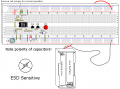
ILLUSTRATION

INSTRUCTIONS
NOTE! This project uses a static sensitive part, the CMOS 555. If you do not use protection as described in Volume 3, Chapter 9, ElectroStatic Discharge, you run the risk of destroying it.
The circuit shown in the previous experiment, CMOS 555 Long Duration Minimum Parts Red LED Flasher, has one big drawback, which is a lack of LED current control. This experiment uses the same basic 555 schematic and adds transistorized drivers to correct this.
The parts used for this transistor driver are non critical. It is designed to load the TLC555 to an absolute minimum and still turn on Q2 fully. This is important because as the battery voltage approaches 2V the drive from the TLC555 is reduced to its minimum values. Bipolar transistors can be good switches.
Since LEDs can have so much variation R4 should be tweaked to match the specific LED used. The current is limited to 18.5ma with 27Ω and a Vf (LED forward dropping voltage) of 2.5V, an LED Vf of 2.1V will draw 33ma, and a LED Vf of 1.5 will draw 56ma. The latter is too much current, not to mention what that would do for the battery life. To correct this use 47Ω if the Vf is 2.1V, and 75Ω if the Vf is 1.5V, assuming the target current is 20ma.
You can measure Vf by using the jumper shown in red in the illustration, which will turn the LED on full time. You can calculate the value of R4 by using the equation: R4 = (3V-Vf) / 0.02A
It was mentioned in the previous experiment that capacitor C2 extended the life of the batteries. An interesting experiment is to remove this part periodically and see what happens. At first you will notice a dimming of the LED, and after a week or two the circuit will die without it, and resume working in a couple of seconds when it is replaced. This flasher will work for over a month using fresh alkaline AAA batteries.
THEORY OF OPERATION
The CMOS 555 oscillator was explained fully in the previous experiment, so the transistor driver will be the focus of this explanation.
The transistor driver combines elements of a common collector configuration on Q1, along with common emitter configuration on Q2. This allows for very high input resistance while allowing Q2 to turn on fully. The input resistance of the transistor is the ß (gain) of the transistor times the emitter resistor. If Q1 has a gain of 50 (a minimum value) then the driver loads the TLC555 with more than 100KΩ. Transistors can have large variations in gain, even within the same family.
When Q1 turns on 1ma is sent to Q2. This is more than enough to turn Q2 fully, which is referred to as saturation. Q2 is used as a simple switch for the LED.
Illustrations: Complete
Experiments: Schematic verified, duration test running since 2/15/09 7AM.
……………..5/16/09 - Flasher still going, has been dimming steadily for the last 2 months. Still usable, but less than ½ brightness.
……………..5/25/09 - Declared dead. It is still flashing, but about 10% brightness.
***********************************************************
CMOS 555 LONG DURATION RED LED FLASHER
PARTS AND MATERIALS
- Two AAA Batteries
- Battery Clip (Radio Shack catalog # 270-398B)
- One CMOS TLC555 timer IC (Radio Shack catalog # 276-1718 or equivalent)
- Q1 - 2N3906 PNP Transistor (Radio Shack catalog #276-1604 (15 pack) or equivalent)
- Q2 - 2N2222 NPN Transistor (Radio Shack catalog #276-1617 (15 pack) or equivalent)
- D1 - Red light-emitting diode (Radio Shack catalog # 276-041 or equivalent)
- C1 - 1 µF Tantalum Capacitor (Radio Shack catalog 272-1025 or equivalent)
- C2 - 100 µF Electrolytic Capacitor (Radio Shack catalog 272-1028 or equivalent)
- R1 - 1.5 MΩ ¼W 5% Resistor
- R2 - 47 KΩ ¼W 5% Resistor
- R3 - 2.2 KΩ ¼W 5% Resistor
- R4 - 27 Ω ¼W 5% Resistor (or test select a better value)
- One DVM or VOM
CROSS-REFERENCES
Lessons In Electric Circuits, Volume 1, chapter 16: Voltage and current calculations
Lessons In Electric Circuits, Volume 1, chapter 16: Solving for unknown time
Lessons In Electric Circuits, Volume 3, chapter 4 : Bipolar Junction Transistors
Lessons In Electric Circuits, Volume 3, chapter 9 : ElectroStatic Discharge
Lessons In Electric Circuits, Volume 4, chapter 10: Multivibrators
LEARNING OBJECTIVES
- Learn a practical application for a RC time constant
- Learn one of several 555 timer Astable Multivibrator Configurations
- Working knowledge of duty cycle
- How to handle ESD sensitive parts
- How to use transistors to improve current gain
- How to calculate the correct resistor for a LED
SCHEMATIC DIAGRAM
ILLUSTRATION
INSTRUCTIONS
NOTE! This project uses a static sensitive part, the CMOS 555. If you do not use protection as described in Volume 3, Chapter 9, ElectroStatic Discharge, you run the risk of destroying it.
The circuit shown in the previous experiment, CMOS 555 Long Duration Minimum Parts Red LED Flasher, has one big drawback, which is a lack of LED current control. This experiment uses the same basic 555 schematic and adds transistorized drivers to correct this.
The parts used for this transistor driver are non critical. It is designed to load the TLC555 to an absolute minimum and still turn on Q2 fully. This is important because as the battery voltage approaches 2V the drive from the TLC555 is reduced to its minimum values. Bipolar transistors can be good switches.
Since LEDs can have so much variation R4 should be tweaked to match the specific LED used. The current is limited to 18.5ma with 27Ω and a Vf (LED forward dropping voltage) of 2.5V, an LED Vf of 2.1V will draw 33ma, and a LED Vf of 1.5 will draw 56ma. The latter is too much current, not to mention what that would do for the battery life. To correct this use 47Ω if the Vf is 2.1V, and 75Ω if the Vf is 1.5V, assuming the target current is 20ma.
You can measure Vf by using the jumper shown in red in the illustration, which will turn the LED on full time. You can calculate the value of R4 by using the equation: R4 = (3V-Vf) / 0.02A
It was mentioned in the previous experiment that capacitor C2 extended the life of the batteries. An interesting experiment is to remove this part periodically and see what happens. At first you will notice a dimming of the LED, and after a week or two the circuit will die without it, and resume working in a couple of seconds when it is replaced. This flasher will work for over a month using fresh alkaline AAA batteries.
THEORY OF OPERATION
The CMOS 555 oscillator was explained fully in the previous experiment, so the transistor driver will be the focus of this explanation.
The transistor driver combines elements of a common collector configuration on Q1, along with common emitter configuration on Q2. This allows for very high input resistance while allowing Q2 to turn on fully. The input resistance of the transistor is the ß (gain) of the transistor times the emitter resistor. If Q1 has a gain of 50 (a minimum value) then the driver loads the TLC555 with more than 100KΩ. Transistors can have large variations in gain, even within the same family.
When Q1 turns on 1ma is sent to Q2. This is more than enough to turn Q2 fully, which is referred to as saturation. Q2 is used as a simple switch for the LED.
Last edited: