Facebook
 Google
 GitHub
 Linkedin
Status: WIP
Illustrations: WIP
Experiments: Pending
****************
555 PULSE WIDTH MODULATION OSCILLATOR
PARTS AND MATERIALS
CROSS-REFERENCES
Lessons In Electric Circuits, Volume 3, Chapter 3, Section 12, Special-purpose diodes, Light Emitting Diodes
Lessons In Electric Circuits, Volume 3, Chapter 11, Section 1, Pulse Width Modulation
LEARNING OBJECTIVES
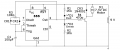
SCHEMATIC DIAGRAM
Here is one way of drawing the schematic:

As mentioned in the previous experiment, there is also another convention, shown below:

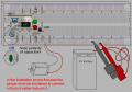
ILLUSTRATION

INSTRUCTIONS
This is one of the most basic of PWM generators a 555 can make. It works, but it has some minor problems. One of them is the frequency is not completely stable. It also varies between 5% to 95%, the edges are not clearly defined due to the diodes dropping voltage and having some internal resistance. Within its limitations it works pretty well though, so it is a popular design.
I have two different capacitors in the design so you can see how the circuit works using LEDs, and for one of the more common uses, that of a motor controller. Start with the 100µF capacitor in the circuit for C1. This will bring the frequency to approximately 0.7 Hz, which humans can easily see.
As you vary R3 over it's range you should see the length of time for each LED vary, and you will also note that the longer one LED is on the shorter time the other LED stays on. This is core to PWM. Ideally the frequency will stay the same, only duration of on/off time changes.
Replace C1 with the 0.1µF capacitor. This will increase the frequency one thousand times, to approximately 700Hz. You might be able to see some flicker from the LED, but nothing more. The on/off ratios of the output will be the same as with the slower flash rate, and at higher frequencies this flicker will disappear entirely. The LEDs intensity will appear to vary in a linear way. This is an important use for PWM, since LEDs are not very linear devices. Yet, we now have two LEDs acting as if they were linear.
The motor will also do something interesting. You may want to fold a piece of tape over the shaft to get a good view of what is going on. You can now vary the speed of the motor from very slow to full speed with fair precision. You are doing this without a gear box, only with electronics, which has many significant implications. Again, a system that is not very linear is acting as if it were.
A motor can be thought of as a specialized inductor. When power is cut off abruptly it can generate a high voltage spike. Given that there is also internal switching going on with any conventional DC motor it will be generating a lot of spikes just turning over. These spikes can damage solid state electronics such as Q1. To prevent this CR3 has been added, when the spike of voltage (which is a different polarity than the power supply) the diode harmlessly absorbs this as current, and Q1 is saved.
R4 prevent there being a really low ohmage between the output of the 555 and capacitor C1. When a capacitor starts to charge it resembles a dead short. Without R4 the 555 could actually get hot and be damaged, but the extra resistor brings that under control, in the process also protecting R3, the potentiometer.
Theory of Operation
This circuit is a modified Hysteresis Oscillator, but uses diodes CR1 and CR2 to steer the current during each side of the cycle. Since the total resistance of R3 stays a constant, the frequency is relatively stable. However, the diodes do interact with the circuit, so some variation in frequency does occur. If the diodes had no voltage drop this would not be the case.
When the output is high the current goes through the left side of R3 and CR1 to charge C1. This sets the length of time the output stays high. When the upper 2/3 set point is reached the output is switched low.

The capacitor C1 discharges through the right side of R3 and CR2. This sets the length of time the output stays low. When the lower 1/3 set point is reached the output is switched high, and the process repeats.

LEDs are not linear to current, but this PWM circuit will make them appear so, which is one of the reasons PWM is so popular controlling LEDs.
Illustrations: WIP
Experiments: Pending
****************
555 PULSE WIDTH MODULATION OSCILLATOR
PARTS AND MATERIALS
- One 9V Battery
- Battery Clip (Radio Shack catalog #270-325)
- Mini Hook Clips (soldered to Battery Clip, Radio Shack catalog #270-372)
- One 555 timer IC (Radio Shack catalog #276-1723)
- Q1 - 2N2222 (Radio Shack catalog #276-1617 15 Pack or equivalent)
- CR1-3 - 1N4001 (Radio Shack catalog #276-1101 or equivalent)
- D1 - Red light-emitting diode (Radio Shack catalog #276-041 or equivalent)
- D2 - Green light-emitting diode (Radio Shack catalog #276-022 or equivalent)
- R1,R2 - 1 KΩ 5% 1/4W Resistors
- R3 – 10 KΩ Potentiometer, PCB Style (Radio Shack catalog #271-282 or equivalent)
- R4 - 10 Ω 5% 1/4W Resistor
- R5 - 470 Ω 5% 1/4W Resistor
- C1 - 0.1 µF Capacitor (Radio Shack catalog #272-1069 or equivalent)
- C1 - 100 µF Capacitor (Radio Shack catalog #272-1028 or equivalent)
- C2 - 220 µF Capacitor (Radio Shack catalog #272-1017 or equivalent)
- M1 - 7.5 VDC Motor (Radio Shack catalog #276-046 or equivalent)
CROSS-REFERENCES
Lessons In Electric Circuits, Volume 3, Chapter 3, Section 12, Special-purpose diodes, Light Emitting Diodes
Lessons In Electric Circuits, Volume 3, Chapter 11, Section 1, Pulse Width Modulation
LEARNING OBJECTIVES
- How to use a Schmitt Trigger for a simple RC Oscillator.
- How diodes can be used to steer currents.
- How to have two RC time constants with one RC.
- Learn one of many 555 timer astable multivibrator configurations.
SCHEMATIC DIAGRAM
Here is one way of drawing the schematic:
As mentioned in the previous experiment, there is also another convention, shown below:
ILLUSTRATION
INSTRUCTIONS
This is one of the most basic of PWM generators a 555 can make. It works, but it has some minor problems. One of them is the frequency is not completely stable. It also varies between 5% to 95%, the edges are not clearly defined due to the diodes dropping voltage and having some internal resistance. Within its limitations it works pretty well though, so it is a popular design.
I have two different capacitors in the design so you can see how the circuit works using LEDs, and for one of the more common uses, that of a motor controller. Start with the 100µF capacitor in the circuit for C1. This will bring the frequency to approximately 0.7 Hz, which humans can easily see.
As you vary R3 over it's range you should see the length of time for each LED vary, and you will also note that the longer one LED is on the shorter time the other LED stays on. This is core to PWM. Ideally the frequency will stay the same, only duration of on/off time changes.
Replace C1 with the 0.1µF capacitor. This will increase the frequency one thousand times, to approximately 700Hz. You might be able to see some flicker from the LED, but nothing more. The on/off ratios of the output will be the same as with the slower flash rate, and at higher frequencies this flicker will disappear entirely. The LEDs intensity will appear to vary in a linear way. This is an important use for PWM, since LEDs are not very linear devices. Yet, we now have two LEDs acting as if they were linear.
The motor will also do something interesting. You may want to fold a piece of tape over the shaft to get a good view of what is going on. You can now vary the speed of the motor from very slow to full speed with fair precision. You are doing this without a gear box, only with electronics, which has many significant implications. Again, a system that is not very linear is acting as if it were.
A motor can be thought of as a specialized inductor. When power is cut off abruptly it can generate a high voltage spike. Given that there is also internal switching going on with any conventional DC motor it will be generating a lot of spikes just turning over. These spikes can damage solid state electronics such as Q1. To prevent this CR3 has been added, when the spike of voltage (which is a different polarity than the power supply) the diode harmlessly absorbs this as current, and Q1 is saved.
R4 prevent there being a really low ohmage between the output of the 555 and capacitor C1. When a capacitor starts to charge it resembles a dead short. Without R4 the 555 could actually get hot and be damaged, but the extra resistor brings that under control, in the process also protecting R3, the potentiometer.
Theory of Operation
This circuit is a modified Hysteresis Oscillator, but uses diodes CR1 and CR2 to steer the current during each side of the cycle. Since the total resistance of R3 stays a constant, the frequency is relatively stable. However, the diodes do interact with the circuit, so some variation in frequency does occur. If the diodes had no voltage drop this would not be the case.
When the output is high the current goes through the left side of R3 and CR1 to charge C1. This sets the length of time the output stays high. When the upper 2/3 set point is reached the output is switched low.
The capacitor C1 discharges through the right side of R3 and CR2. This sets the length of time the output stays low. When the lower 1/3 set point is reached the output is switched high, and the process repeats.
LEDs are not linear to current, but this PWM circuit will make them appear so, which is one of the reasons PWM is so popular controlling LEDs.
Last edited: