Sub woofer Circuit made with a tda2030a ic

Thread Starter

dbain24

Joined Mar 29, 2019
4
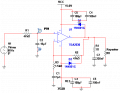
Good afternoon i am senior design student building a power audio amplifier and i'm having problems with my sub woofer circuit, every time i have put voltage to the to activate the pins 5 and 3 either the ic burns up or the 1 ohm resistor burns up. could it be that the 1 ohm resistor needs to be 10 watts rated and that is causing the components to burn or could it the dc power supply i am using instead of 15 V batteries is delivering too much current to the ic pins 3 and 5? or is the proposed circuit has errors in it that is causing the burning of the components. your help would be greatly appreciated. the sub-woofer circuit is attached.
 

Attachments

crutschow

Joined Mar 14, 2008
34,283
Or it could be the circuit is oscillating.

Is this constructed on a plug-in breadboard?
If so, such a breadboard has a lot of stray capacitance, which can cause high-frequency oscillations.
Much better to build it on a Vector type breadboard.

Are those decoupling caps (C4 through C6) directly connected to the IC power pins?
 
Last edited:

MisterBill2

Joined Jan 23, 2018
18,176
Crutschow is right. That IC will oscillate at a high amplitude and fail quickly under many conditions. So the very first step is to read and understand the manufacturers application notes, especially the parts about bypassing and avoiding lead inductance and ground loop problems. When you see the commercial products with these the bypass caps are very close to the pins, usually within 0.15 inch, or 2mm. And for checking initially, use a power source with very limited power, so as to avoid destroying things when it oscillates. those 100nF caps should have short leads and the ground plane should be nearby. Look at the circuit board layout in the application notes because the folks who did that design know what it has to provide.
 

Thread Starter

dbain24

Joined Mar 29, 2019
4
any other suggestions other than that. i am going to try out what u guys said today in the lab, and do you guys have any circuit ideas i could use for a crossover circuit to add to the power audio amplifier.
 

crutschow

Joined Mar 14, 2008
34,283
Why do you have so much amplifier gain (32.3) as determined by R2 and R3?
Your 1Vrms input will clip the output (about 14V max) by more than a factor of 3.
Such a high gain will also make the amp more likely to oscillate.
The gain should probably be about 10 or less.

Edit: R1 and C2 form a low-pass filter with a corner frequency of about 20Hz, meaning frequencies above that are rolled off, which makes no sense. :confused:
 
Last edited:

crutschow

Joined Mar 14, 2008
34,283
so i will change the 47k to a 10k and let u know how it goes.
Who is this "u" person? :rolleyes:
If that rolloff allows too much of the higher frequencies through the sub, you will need to go to a higher order filter.

Below is a 3-pole active filter configuration that should work for the TDA2030, which gives a much sharper rolloff [18dB/octave (blue trace) vs 6dB/octave from the 1-pole (yellow trace)].
I reduced the gain to 10.

upload_2019-4-2_11-42-30.png

You didn't explain why you have the gain so high. :confused:
 
Last edited:

DickCappels

Joined Aug 21, 2008
10,152
The TDA2030 is very much like a high powered opamp with a small offest voltae. You need to bias the input up to somewhere around Vcc/2 and put a capacitor in series with the output to 1) prevent clipping off of the negative part of the signal and 2) stop burning your 1 ohm resistor.

Note how the biasing is done on the left side of this full bridge implimentation from the Philips data sheet. Being full bridge obviates the need for AC coupling on the output.

upload_2019-4-3_5-8-45.png
 

PeteHL

Joined Dec 17, 2014
473
The data sheets for TDA2050 specify voltage gain of the IC must be greater than 16. This most likely also applies to TDA2030. In an article that I have briefly describing both ICs, voltage gain of both of them is given as 30 dB.
 

Audioguru

Joined Dec 20, 2007
11,248
I agree that the amplifier IC is oscillating at a very high frequency because it is built in a tangled mess of wires on a solderless breadboard, instead of built neat and tidy on a printed circuit board.

Hey, the old TDA2030A is obsolete and is not made anymore. Are you allowed to use that old thing? From where will you get one? A Chinese copy that doesn't work?
 

Audioguru

Joined Dec 20, 2007
11,248
But why do you have the gain at over 30?
He uses a 30V supply and the datasheet for the TDA2030A shows 10.2W into 8 ohms which is 9VAC RMS. With a gain of 32 times then the input must be 9V/32= 281mV which is a little less than consumer line level (316mV RMS). If I made this amplifier then I would make it with a preamp having a gain of 4 times.
 
Top