 Facebook
 Google
 GitHub
 Linkedin
Hello Folks
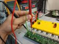
I am running out of ideas. I have designed a PCB with three Traco Power switching regulators: TSR1 2450. After an initial test with the three SW Regulators mounted, the PCB was broken because an overcurrent. Then I isolated one SW regulator in a Protoboard (see Pic1) and the SW regulator regulated the voltage rightly (Vin=10V, Vout=5V).
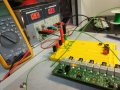
However when I mounted again the same regulator on the board (see Pic 2), the SW regulator did not work properly and I measured the output voltage and it was the same voltage (aprox.) like the input voltage (Vin=10V, Vout=9.6V). It is like the regulator short circuits the input with the output. Anyone has any idea about what can it be happening?.
Thanks in advance.
I am running out of ideas. I have designed a PCB with three Traco Power switching regulators: TSR1 2450. After an initial test with the three SW Regulators mounted, the PCB was broken because an overcurrent. Then I isolated one SW regulator in a Protoboard (see Pic1) and the SW regulator regulated the voltage rightly (Vin=10V, Vout=5V).
However when I mounted again the same regulator on the board (see Pic 2), the SW regulator did not work properly and I measured the output voltage and it was the same voltage (aprox.) like the input voltage (Vin=10V, Vout=9.6V). It is like the regulator short circuits the input with the output. Anyone has any idea about what can it be happening?.
Thanks in advance.
Attachments
-
 172.8 KB Views: 10
 -
 198.6 KB Views: 10
")


