Strange digital clock dilemma

Status
Not open for further replies.

Thread Starter

Arjune

Joined Jan 6, 2018
234
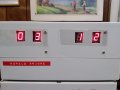
The cmos digital clock that I built that I have in my room where I live in an adult home changes time when I plug or unplug the power cord. There is a nine volt battery backup. When I set the time with the power cord in sometimes the time would go ahead unexpectedly. I am powering the clock externally with a self-made 12 volt power supply using a 7912 voltage regulator. It is using CMOS counters and display drivers and OR and AND Gates and also CMOS inverters. I brought the clock to my mother's home in the Bronx for a visit and I noticed that when I plug and unplug the power cord the time remains the same and I don't have the dilemma. Could it be that some type of signal is being sent through the power line in the adult home that is disrupting the 120v ac power line that disrupts the clock? The adult home does have an elevator that operates all the time that may be 240 volts at three phase. Any thoughts? Before you guys told me to add .1uf bypass capacitors to the power terminals of the ICS but I didn't do that since the clock works good in the Bronx at my mother's home. Most of us, including me, are schizophrenics in the adult home and I'm thinking that somebody is sending a signal through the power line to do something wrong to us because of the clock's evidence. Another thought that I had is that the AC line voltage is not grounded properly but that would seem impossible according to reality. Would my psychiatrist be able to explain the problem? I really doubt it since they don't reinforce my paranoia.
 

MrSalts

Joined Apr 2, 2020
2,767
It's always easy to say don't be paranoid but, let's look at the situation. Sending signals through power lines was one of the first home automation methods - a protocol called X-10 and introduced in the early 1990s (maybe the 1980s). But today, it is much easier and safer to use internet protocols and Bluetooth or other 900MHz or 2.4GHz wireless protocols rather than push information through a power line. The X-10 wasn't even really sending data, it was essentially sending a single on/off instruction for a lamp or an appliance. Several companies tried to use power lines for sending internet through your home in the late 1990s but that soon came to an end as everyone started using wiFi and realizing that mixing power lines and internet was a bad idea because the power protection for power line surges from lighting strikes or other surges can kill a motherboard pretty easily.

so, to your question,first, look at the outlet used in your Adult home to see if both vertical connectors are the same size or if one is larger (a polarized outlet). Then compare to see if the outlet at your mother's home is the same or different. I'm guessing one location has one type (polarized) and the other is non-polarized. I think the polarized (safety) outlet is likely required in a modern home or in a renovated medical facility (group home) and this polarized outlet is designed to connect to neutral first, then as you finish plugging in all the way, the live wire connects. This causes a different kind of pulse in the clock than a non-polarized plug that may be at your mother's house where the live wire may be connecting first (before neutral) and creating a different effect in the clock (not causing the hour to jump).
Who knows? There are many possibilities beyond this first suggestion.

Another difference, some older homes in the Bronx don't even have grounding wires or a grounding rod right next to the fuse box. The elevator you mentioned may be making surges is also a good thought. Even the local voltage - your mother may be living in an area of slight brown-out (lower supply voltage) than the voltage at the Adult home. Also, some cheap digital clocks (digital anything) don't have proper pull-up resistors at switches. Pull-up resistors help make sure an input is clearly read by a logic gate or microcontroller input as a HIGH (when the switch is open) or a LOW (when the switch is closed). Without a proper pull-up resistor, the input logic gate can be sensitive to static or poor grounding.

without looking at the clock, both locations, doing experiments and Ruling out various ideas, there is no way to give a perfect answer. But rather than make up unusual possibilities, I feel confident in telling you that a poor electrical design of the clock or different AC electric equipment is likely causing the clock to behave differently at the two locations.
 

Thread Starter

Arjune

Joined Jan 6, 2018
234
The problem with the clock is not at my mother's home but the adult home. The adult home and my mother's home have polarized outlets and when I tested the outlet at my mother's home there is no indication that the neutral side is making contact first with the plug but both the neutral and live sides of the plug contact the outlet terminals at the same time when the plug is pushed in. I am assuming the same outlet design is at the adult home. I am thinking that some kind of signal is coming in with the 120 volt AC of the outlet on both the live side and the neutral side irrespective of whether the neutral or live side of the plug makes contact first with the outlet. Both outlets at my adult home and my mother's home are grounded so what if I connected two capacitors between the neutral and the ground and the live and the ground connected to a grounded plug? I'm guessing that the capacitors I would put would be 0.1uf at 400 volts.
 

AlbertHall

Joined Jun 4, 2014
12,343
The problem with the clock is not at my mother's home but the adult home. The adult home and my mother's home have polarized outlets and when I tested the outlet at my mother's home there is no indication that the neutral side is making contact first with the plug but both the neutral and live sides of the plug contact the outlet terminals at the same time when the plug is pushed in. I am assuming the same outlet design is at the adult home. I am thinking that some kind of signal is coming in with the 120 volt AC of the outlet on both the live side and the neutral side irrespective of whether the neutral or live side of the plug makes contact first with the outlet. Both outlets at my adult home and my mother's home are grounded so what if I connected two capacitors between the neutral and the ground and the live and the ground connected to a grounded plug? I'm guessing that the capacitors I would put would be 0.1uf at 400 volts.
For good safety the capacitors should be X2 rated (for continuous connection to the AC supply).
And perhaps aslo connect one between live and neutral.
 

Deleted member 115935

Joined Dec 31, 1969
0
As I read this
what you have is a start up / switch over problem,

A capacitor filter as described, might make things better, and it wont make it worse, but it might not be "the fix"

I'd be looking at a power up reset circuit on the mains PSU side,
such that you don't allow a switch over to happen till the power is clean and stable for a while,
 

Thread Starter

Arjune

Joined Jan 6, 2018
234
I'm assuming that PSU means power supply unit and the mains side means the outlet. Can you please give me an example of a power up reset circuit schematic. I'm thinking I plug my power supply line cord into the output of the power up reset circuit and the input of the power up reset circuit goes to the outlet.
 

Deleted member 115935

Joined Dec 31, 1969
0
I'm assuming that PSU means power supply unit and the mains side means the outlet. Can you please give me an example of a power up reset circuit schematic. I'm thinking I plug my power supply line cord into the output of the power up reset circuit and the input of the power up reset circuit goes to the outlet.
A power up reset,
sits on your circuit board,

I might have miss understood, Can i check, is this your own clock design or a unit ?
 

Thread Starter

Arjune

Joined Jan 6, 2018
234
clockpwr.png
I am now using a grounded plug for the AC and so far the power supply works good in my mother's home here in the Bronx. When I go back to Rockland on Tuesday at the adult home I plan to try the power supply with the clock there to see if I have a problem. The 10 ohm 2 Watt resistor could be a safety hazard right? The transformer is 12V at 500mA. I just realized that I need a fuse on each grounded capacitor, not just one on both.
 

AnalogKid

Joined Aug 1, 2013
10,986
Why is there a 10 ohm resistor in the primary side of the power transformer?

The fact that the clock behaves differently in different locations indicates to me a sensitivity to some noise component on the incoming power line. It could be nothing more than a noisy fluorescent light ballast. Whatever it is, the first step in combating it is assuring good power quality at each chip.

To do this, install the decoupling caps. Nothing else will be easier to do and have a higher chance of success.

ak
 

Deleted member 115935

Joined Dec 31, 1969
0
I get impression you have idea that there is "noise" on the mains, and the resistor and capacitors are your idea at fixing ?

Do I understand that its when you plug in / un plug mains that the "disruption" happens,

If so ,

I'd suggest, take off those capacitors and resistor ,

ground is always a god thing to have,
apart from when I was in Italy, where the ground was at 110 V ? ( nice free power source !! )

Power on reset.

How have you connected the local battery backup and the 12 v "switchover"

When you plug in, the 12v power can be very "unsteady" for a while

A power up reset controller is something like the TL7702A

It monitors the 12 v you have,
and it has an output that a certain time after the 12v is good, generates a "good" signal,

You use this output to tell your circuit to use the now stable 12v not the battery backup,
If your using a processor for the clock, this signal is the reset into the processor,

without the circuit diagram, we cant give you more detailed advice as to what to do,
 

Thread Starter

Arjune

Joined Jan 6, 2018
234
Being a schizophrenic the 10 ohm resistor is because of my personality "sick" feeling that it is being deceived and logically it's just to have more control of the primary fluctuations of the transformer in tandem with the 0.1uF capacitor to neutral. I know lots of you are strong in your beliefs but I just can't put 19 (nineteen) 0.1 microfarad capacitors on IC power terminals on circuit boards that has so little pad area because I could damage my circuit board then I would have a serious problem worse than what I'm trying to solve. I sort of have a positive feeling about the grounded plug and if the ground terminal makes contact with the socket first when I put it in hopefully before the return and the hot then I think the problem might be resolved. Anomalies could change the perception of belief and change the physical evidence to make things malfunction. I don't think anything in the secondary of the transformer will work because of very fast transients in the primary so I don't think I want to use a power-up reset circuit since I think this is something spiritual I'm dealing with. I think the best I can do is try the circuit I have at my adult home.
 

Deleted member 115935

Joined Dec 31, 1969
0
Sorry

never heard of a power up reset being called "spiritual",

Good luck in your interesting technique,
 

dl324

Joined Mar 30, 2015
16,839
Last edited:

AnalogKid

Joined Aug 1, 2013
10,986
I know lots of you are strong in your beliefs
I understand where you are coming from, and I'm not trying to pick a fight. But ...

These are not beliefs. These are facts that are rooted in the physics of electric and magnetic fields, electron flow through a conductor, noise propagation through a power supply, and the effects of a power supply's non-zero source impedance on the stable operation of integrated circuits. My personal background is over 50 years of analog and digital circuit design in a wide variety of application areas (professional audio and video, industrial controls, etc.) with the last 20 years dealing with extremely high noise in military environments. Decoupling capacitors work. They can't fix everything all the time, but they do fix a lot of things a lot of the time.

ak
 

LesJones

Joined Jan 8, 2017
4,174
Hi dl324, I was hoping to see a full schematic showing decoupling capacitors and the power supply wiring. From the description its sounds like the clock has a built in mains power supply, a socket for it to be supplied from an external 12 volt DC power source. It also has a 9 volt battery backup which I assume supplies a crystal controlled clock and the rest of the cmos logic but does not supply the the LED displays.
I agree that decoupling capacitors are required close to the ICs on the supply lines. I would also like to see how the power is routed from the different power sources.

Les.
 

DickCappels

Joined Aug 21, 2008
10,153
Careful! You are injecting nearly 5 ma into the ground pin through that 0.1 uf capacitor from the (I suspect) 120 VAC. If this were a commercial product and 5 ma ground leakage were detected, an alarm would sound and the entire production line could come to a halt. Don't mean dramatic, but I've see it happen. If you want to use a capacitor from Line to ground, please keep it much lower both for my peace of mind and your safety :)

One thing I would try right away to solve the "power supply glitching problem" is to put a much larger capacitor across the 470 uf, like and additional 2200 uf, and see whether that solves the problem. The idea is that the larger capacitor would hold the power supply "up" while the glitch settled.

Do you know how much current is going into your 7812 and what the normal DC voltage into it is?
 

Deleted member 115935

Joined Dec 31, 1969
0
I hope Im wrong
but Im getting a smell of fish here.

The OP said they have a battery backup / plug into mains problem,

If the above circuit is the one they are talking about,
then there is no crystal or other circuit to create a precise clock as needed by a useful clock

Im wondering how the LDO can be supplying the current for those LEDs
how much of a heat sink would it need ?

As for the battery backup mentioned by the OP.
there is no circuit to load the drivers with a value from say a RTC chip, which would be low power.

so the OP would have to keep the digital chips powered off the battery,
Lets hope they manage to turn off the leds to at least save that energy.

Then the OP is and has posted in multiple forums overlapping each other,
yet when asked, they do not give references to these other forum posts,
nor do they even supply the schematic diagram , which it seems they had as posted by some one else above,

All very funny smell,

come on back to us please,
 
Status
Not open for further replies.
Top