 Facebook
 Google
 GitHub
 Linkedin
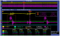
Sitting idle my pwm from my dsPIC works fine but when I try to drive my SMPS it looks like the attached image.
I dont want to suggest anything because I dont want to bias anything anyone says. I am also trying to learn as well.
Thank you!
I dont want to suggest anything because I dont want to bias anything anyone says. I am also trying to learn as well.
Thank you!
Attachments
-
 275.3 KB Views: 33
 -
 78.6 KB Views: 23


