Wires 2 and 5 are your +V supply connections. Label them as such; "+V" is sufficient.
Arbitrarily label wires 1, 3, 4, 6 as A, B, C, and D.
It appears to be a unipolar stepper motor.
You don't know which is the end of what coil at the moment. It will take experimentation to determine what order you will need to energize (ground) the winding ends in order to rotate (step) the motor.
canon QH4-4115: the one above all.
1 to 2 measures (Ohms/NC): 70 1 to 3 measures (Ohms/NC):140 1 to 4 measures (Ohms/NC):140 1 to 5 measures (Ohms/NC):140 2 to 3 measures (Ohms/NC): 73 2 to 4 measures (Ohms/NC): 71 2 to 5 measures (Ohms/NC): 73 3 to 4 measures (Ohms/NC):140 3 to 5 measures (Ohms/NC):141 4 to 5 measures (Ohms/NC):140
Wire 2 is the +V wire.
Label it as such.
Arbitrarily label wires 1, 3, 4, 5 as A, B, C, D.
It appears to be a unipolar stepper motor with a single common supply.
so again :
for your opinion which driver I need to build for drivering this motors??
You do not know the current rating for the motors.
Locating a datasheet will solve that mystery. For the moment, assume a 12v supply.
For the 42SIN-15D9NA motor, 12v/40 Ohms = 300mA. If you want to play it safe (good idea) then use a 30 Ohm 10W resistor between this motor's +V wires and 12v. You could use three 10 Ohm 5W resistors in series, or three 100 Ohm 3W resistors in parallel.
For the canon QH4-4115 motor, 12v /70 Ohms = 171mA.
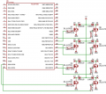
You can use a ULN2803A eight-channel Darlington driver to control the motors.
Connect the COM terminal (pin 10 of the ULN2803A) to +V (12v).
Connect the 8 inputs directly to an 8-bit I/O port on your uC.
Connect the ABCD wires individually to outputs of the ULN2803A.
Connect the +V wires of the motors to +12v.
Connect the GND pin (9) of the ULN2803A to ground.
Re-write them in binary, and you will see what I mean.
To use full step, the sequence goes like:
0001
0010
0100
1000
...etc
To use half step, the sequence goes like:
0001
0011
0010
0110
0100
1100
1000
1001
...etc.
You really have no idea how long it will take to execute the T() subroutine, do you?
However, you are shooting yourself in the proverbial foot by hard-coding the statements.
You could instead define an array of type char() that is eight bytes long.
Then manipulate the index to the array.
But, this is off-topic. You need to take this up in the uC and embedded forum.
You are looking at the datasheet for the L297. That is a controller for a bipolar stepper motor driver, the L298.
You have a couple of unipolar motors. I have shown the correct stepping sequences for unipolar motors in my prior post. Unipolar motors are easier to drive than bipolar stepper motors. If you wish to go to all of the extra trouble, you MIGHT be able to use them as bipolar steppers; but you would probably need more than 12v to drive them at a decent stepping rate.
The 42SIN-15D9NA will be more difficult to determine on how to use as a bipolar, as the center taps are tied together - unless you can supply more accurate resistance measurements, it will be mainly test, then swap wires (or modify program).
Earlier I mentioned the ULN2803A. If you only wish to use full stepping, it will be adequate. However, if you are going to be using half-stepping on both motors, you will need a more capable IC.
The ULN2066 and ULN2068 are ICs that contain four Darlington channels that are capable of 1.5A sink current each. They are about $3.09 each from Digikey. You would need one per motor.
You COULD use the MOSFETs that I initially suggested. You would need four per motor. You would also need to use fast-recovery diodes from the source terminals to +V.
so you are saying that I need more powerful transistors for half step mode. and I thing I would go on it. it will be more accurate.
this is the Sequence :
can you uplode the schematic of fast-recovery diodes?

 Facebook
 Google
 GitHub
 Linkedin