 Facebook
 Google
 GitHub
 Linkedin
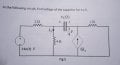
Guys can you please help me with this. I have to hand this in tomorrow.

I'm looking for the voltage at that capacitor in the middle. Usually I do an open source KVL on it. I'm not sure if it's 14 or 0?
Could someone just please tell me. I'm realllllly short on time guys
I'm looking for the voltage at that capacitor in the middle. Usually I do an open source KVL on it. I'm not sure if it's 14 or 0?
Could someone just please tell me. I'm realllllly short on time guys


")


