 Facebook
 Google
 GitHub
 Linkedin
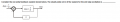
Refer the attached image.
My solution:-
Error--> E(s)=R(s)-C(s)
=R(s)-[G(s)/1+G(s)H(s)]*R(s)
where H(s)=2
Steady state error--> e=lim s.E(s) ....where s approaches zero(final value theorem)
So my solution gives value e=0.5
But the actual answer is e=0.
And the sample solution takes
E(s)=R(s)/Kh - C(s)
where Kh is a constant defined as H(0)=2
I don't get it . I had read that even in non unity feedback system we take E(s) as difference between R(s) and C(s). Am I conceptually wrong here?
Attachments
-
 6.1 KB Views: 15


