 Facebook
 Google
 GitHub
 Linkedin
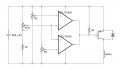
Here is a simple circuit you can build that will do what you've asked. It doesn't require a microprocessor.
You will have to experiment with it to get it to work for you. Here is a basic explanation of how it works.
On the left is your battery, whatever you use to run the fan motor. I guessed that it would be 6 volts. This has to be at least 4.5 volts, and 6 is better, so if you only need 3 volts for your motor, we need to make an adjustment.
The part labeled FSR is your Force Sensitive Resistor. This whole thing depends on what you pick for that. Here one option: http://www.kr4.us/force-sensitive-resistor-long.html?gclid=CJ2o9NTajMoCFYeBfgodxggAgQ
The IC is a LT319A dual comparator, arranged so that it can detect if the voltage from the FSR is inside of a narrow voltage range. The voltage range is set by R2 and R3, where R2 sets the high end and R3 sets the low range. Both of these have to be between 0 and the battery voltage. In this circuit, if the input is between the low and high voltages, the voltage out of the IC will be near zero volts. That will turn on the mosfet (transistor) and power will go to the motor. The main requirement on the mosfet is that it can handle the power to the motor and it needs to be a P-Channel mosfet.
So 15 minutes of thought and here is something you can try. Can you get the parts?
I didn't put values on the resistors, because it might take some experimentation. But I would start with R1-10k, R2, R3-100k, R4-10k, and the diode could be a 1N914. But other parts could work too.
Questions?
Attachments
-
 124.2 KB Views: 14


