The obsolete Mosfets are connected wrong.
The 2SJ162are upside down and they should be on the bottom of the circuit as common drain, not common source.
The 2SK1058 should be at the top of the circuit as common drain, not as common source.
I did not check the phasing.
What a coincidence.
I worked for a company that was the Canadian distributor for NEC large modern business telephone systems.
Suddenly the warehouse became empty and sales became zero. I asked my boss if his company was going bankrupt and he did not answer so I resigned. A few years later I read that he sued NEC for breaking his contract and he won 7 million dollars!
NEC spun off its semiconductor business to Renesas company who sell and make obsolete transistors, and NEC has withdrawn from manufacturing most things.
The phasing is correct. The non-inverting input of the long-tailed pairs drive a buffered, cascoded VAS, which in turn drives a complementary feedback pair output stage with TR21/Tr20/TR24 on the positive supply, and TR21/TR19/TR23 on the negative supply. The MOSFETs should indeed be common source. It has 2-pole compensation.
The 2SJ162s are upside down, but they are correctly on the positive supply. The 2SK1058s are drawn correctly.
The lateral MOSFET is still alive and well, and now made by Exicon and distributed by Profusion. ECX10P20 and ECX10N20 are similar to 2SJ162 and 2SK1058.
The purpose of a star ground is to keep the ground currents from the higher power stages going through the ground for the input/low power stages to get to the supply return.
So you follow the ground currents and pick the point for the star ground accordingly.
So it seems fine the way I designed it using common source. I actually switched around the SJ162 on the PCB its just a schematics that is faulty. Could it be that one of these MOSFETs is not working properly just simply conducting to the output?
Possibly - but you can easily tell - it's gate-source voltage will be zero. If it's gate-source voltage is >2V or so, then the circuitry is switching it on.
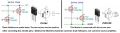
Here is a similar old amplifier circuit from Elliot Sound Products using the same Mosfets as in this thread but they are used as normal common drain followers.
It was designed and tested in 2004 with an update in 2012. 180W into 8 ohms.
OOPS, it has a copyright that says No Copies Allowed. It his project #101. He will not provide a parts list, he says for you to buy his pcb instead.
His design looks very similar indeed, but my source tested the circuit I'm using and he implemented a common source follower. Many designs do implement a common drain follower, but this one is designed differently.
His design looks very similar indeed, but my source tested the circuit I'm using and he implemented a common source follower. Many designs do implement a common drain follower, but this one is designed differently.
A Cmos low power opamp uses common source amplifiers at its output so that its output is "rail-to-rail". Because its output Mosfets have voltage gain then the gain is reduced when loaded.
Class-AB amplifiers using bipolar transistors have output transistors that are always common collector emitter-followers, never common emitter amplifiers because they would be very difficult or impossible to bias with stability.
You said "common source follower" that is wrong, it is a common source amplifier, not follower.
Class-AB amplifiers using bipolar transistors have output transistors that are always common collector emitter-followers, never common emitter amplifiers because they would be very difficult or impossible to bias with stability.
Nonsense - there are loads of complementary feedback pair amplifiers, where the output transistors are common emitter. They are not particularly difficult to bias.
 Facebook
 Google
 GitHub
 Linkedin