Facebook
 Google
 GitHub
 Linkedin
Jerry-Hat-Trick
- Joined Aug 31, 2022
- 833
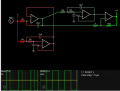
Maybe you could double the frequency with an XOR gate and comparator and use a flip flop to divide the frequency back down again? With the right selection of RC components in the doubler circuit (which won't have a 50% duty cycle) you can probably get this to work and the halved frquency should have a 50% duty cycle..... I think.
But I still prefer the ATtiny85 solution with minimal components and really simple code. I urge you to learn the Arduino IDE, you'll be overwhelmed with ideas about what you can do with it.
But I still prefer the ATtiny85 solution with minimal components and really simple code. I urge you to learn the Arduino IDE, you'll be overwhelmed with ideas about what you can do with it.