Spoiler Emulator- Latching Relays with input polarity reversing

Thread Starter

c131frdave

Joined Jan 14, 2005
19
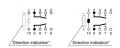
I'm a little confused. Your diagram has two relays, one single coil and one dual. I bought both, but I'm wondering why I need both. I'm also wondering which pin on which relay to use in your diagram. Sorry, I'm a complete novice with electronics. Both Panasonic relays have 10 pins. As I read it, the relay has two power pins, and then two latching relays with NO and NC pins, and the latching relays switch states when the supply polarity changes. Am I missing something? Even the datasheet is confusing. 1742303569369.png
 

Thread Starter

c131frdave

Joined Jan 14, 2005
19
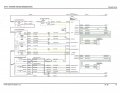
After reviewing the drawing, I think I made a mistake by not including the entire existing circuit in this post for your review. Attached is the entire control for raising and lowering the spoiler. I asked the same question posed in this thread to ChatGPT and it warned not to forget a resistor equal to the motor's resistance in my emulator. Thoughts on that? Thanks!!
 

Attachments

Thread Starter

c131frdave

Joined Jan 14, 2005
19
I think I see why you used two relays now. I thought you could use just the one DPDT and simply reverse polarity to latch the contacts in opposite directions. No? You have to use 2 coil latching between pins 10-6 and 1-5?
 

sghioto

Joined Dec 31, 2017
8,675
The resistor is likely required to emulate the current draw of the motor otherwise the ECU might interpret that as a fault.
I'll look into a drawing on the connections required with that full spoiler circuit.
 

sghioto

Joined Dec 31, 2017
8,675
Because you removed the original spoiler for a fixed one is the motor still installed?
Do you have the switch in the car that manually raises the spoiler for cleaning?
 
Last edited:

sghioto

Joined Dec 31, 2017
8,675
This is how the circuit will be connected to the existing wiring in the vehicle.
The contacts on RL2 replace the two micro switches.
The resistor is not required if the motor is still in the vehicle.
The coils and contacts are labeled with the pin numbers corresponding to their respective relays.
The connections on pin1 and pin10 of RL1 may need to be reversed depending on the polarity of the voltage from the ECU when first activated.
Hopefully this circuit can be tested without the vehicle in motion.
Again this may not work depending on how the ECU monitors the motor.
Do you understand this layout and/or any questions?
1742345671628.png
 
Last edited:

Thread Starter

c131frdave

Joined Jan 14, 2005
19
Oh wow, that's perfect. Thanks so much. To answer your question above, I have a fixed spoiler. I have not removed the motor, but it is disconnected. I left the motor in there in case I wish to switch it back at a later date, but for now I have a fixed spoiler installed. I bought a little project box about the size of a cigarette lighter and the correct connector so I can just plug this in to the cable that currently plugs into the actuator, and then double-sided tape the box next to the actuator.
 
Top